VPL400-X: Install Manual
21JULY2023 | 630-00159 B
22
INSTALLATION
VPL400-X: SECTION 4
INTERLOCKS
The approved interlocks (EMI) are Harmar and
Honeywell. See wiring secons pages 29-31.
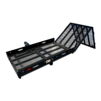
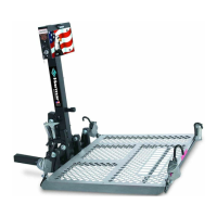
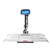
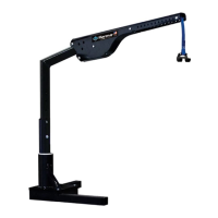
INSTALLING FIXED RAMPS
1.
opening.
2. Anchor the ramp to the concrete pad.
See gure 4-37.
Figure 4-37
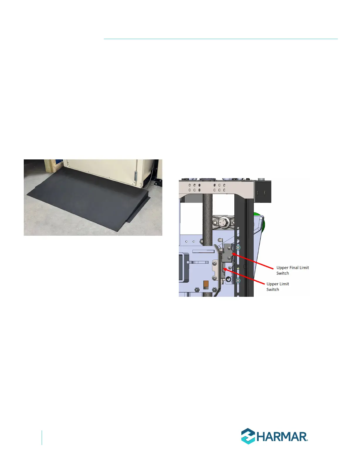
SETTING THE LIMIT
SWITCHES
The upper and lower limit switches are set from the
factory will need to be adjusted based upon the
landing heights at the installation site.
1. Raise the platform so it is level with the upper
landing.
2. Loosen the bolts on the upper limit switch
assembly. Slide the assembly up or down as
needed until the switch makes contact with
the carriage and makes a clicking sound. Re-
tighten the bolts. See Figure 4-38.
Figure 4-38
3. Repeat for lower limit switch.