4 HMX6803+ and OP+HMX+ Installation and Operation Manual
Copyright © 2009, Harris Corporation
Chapter 1: Introduction
Module Descriptions
Front Module
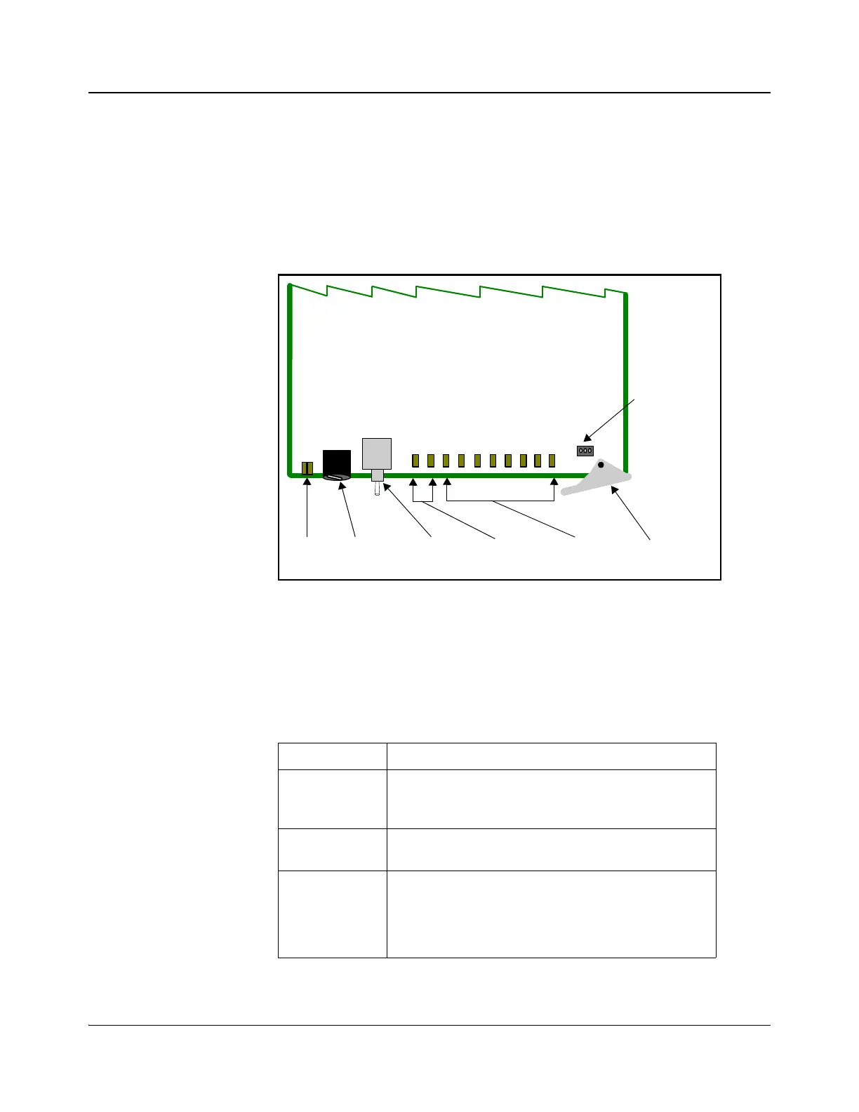
Figure 1-1 is a generic top-front view of a typical 6800+ module and shows the
general location of standard LEDs, controls, and jumpers. The number of
control and monitoring LEDs on 6800+ modules varies.
Figure 1-1. Typical 6800+ Module
Table 1-3 on page 4 briefly describes generic 6800+ LEDs, switches, and
jumpers. See “Chapter 3: Operation” for more information on specific
HMX6803+ and OP+HMX+ module controls, LEDs, and jumpers.
Table 1-3. Generic 6800+ Module Features
Feature Description
Module status
LEDs
Various color and lighting combinations of these LEDs
indicate the module state. See
“Monitoring LEDs” on
page 61 for more information.
Mode select
rotary switch
This switch selects between various control and
feedback parameters.
Navigation
toggle switch
This switch navigates up and down through the available
control parameters:
• Down: Moves down through the parameters
• Up: Moves up through the parameters
Module
status
LEDs
Mode select
rotary
switch
Navigation
toggle
switch
Monitoring
LEDs
Remote/local
control
jumper
Extractor
handle
Control
LEDs