IEI
55
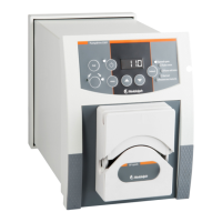
5.1.4.2. Size 2.8 mm tube
fig. 40
Use cone from your hardware kit. Refer to fig. 40 and plug tube through coupling nut, after having
trimmed (pointed) tube end. After installation cut pointed end apart. Install cone as shown, pull
coupling nut hand-tight.
5.2. Cassette medium
Medium-model cassettes exclusively have been designed for C 8 multi-channel
pump heads.
Installation procedure is the same as described for the small-model cassette (refer to chapter 5.1
ff); these cassettes however do not feature stoppers, they use tubes from the reel only (refer to
chapter 15, reference table).
When cassette is interlocked with multi-channel pump head exert some pull force on both ends of
the tube to prevent tube from looping.
To adjust roller
contact pressure, turn setting knob until inboard wedge reads between 3 and 4 on
the scale; refer to chapter 5.1.1 to optimize roller contact pressure.
5.3. Cassette large
Large-model cassettes exclusively have been designed for C 8 multi-channel
pump heads.
Installation procedure is the same as described for the small-model cassette (refer to chapter 5.1
ff); these cassettes however do not feature stoppers, they use tubes from the reel only (refer to
chapter 15, reference table).
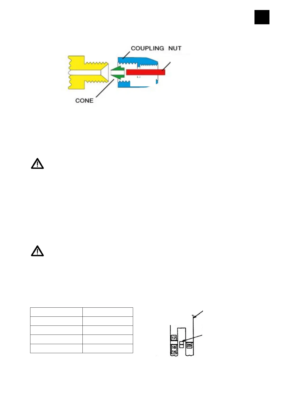
The large-model cassette features adjustable tube retainers on in- and outlet ends. These
retainers adjust tube clamping action for different sizes of tubes. To adj
ust setting knob (61) make
reference to fig. 41 and the reference table below:
size of tube set to
1,7 14
3,1 16
4,8 25
6,3 17
TUBE RETAINER
BUTTON
61
TUBE
 Loading...