- TTL-level 0 V = CW rotation, TTL-level 5 V = CCW rotation.
- A 5 volts TTL signal turns item ON, next signal to follow turns item OFF. This function is
available all the time (in internal mode either).
- For triggering sense of rotation and ON / OFF function, a 5 volts pin is available in the
interface connector which allows potential-free switching.
- The analog interface is recognized at a level of 0.2 volts or a 4 mAmps current; This mode is
confirmed by "EA" in the display. As long as the pump drive is controlled via the analog
interface, "Start/Stop" key will be the only active key on the item.
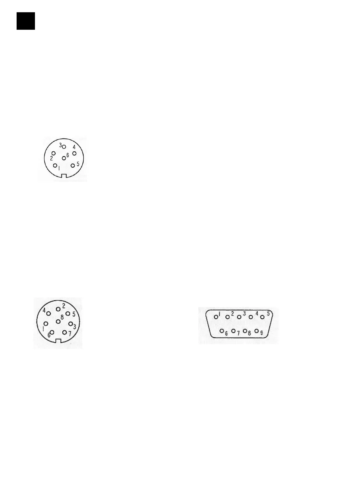
- Wiring of the interface connector (37):
PIN 1 = +5 volts
PIN 2 = start/stop
PIN 3 = 0-10 V
PIN 4 = sense of rotation
PIN 5 = 0 V (GND)
PIN 6 = 4-20 mA
View on terminal end
- Use IP 67 plug connectors only (Binder 6-pin 99-5121-15-06), Heidolph P/N 14-010-006-81,
not to void splash water protection.
- Installation of plug connectors is limited to skilled personnel.
9.4.2. RS 232 interface (fig. 50)
- The RS 232 interface allows pump control from a PC via parallel interface.
- The RS 232 interface connector is installed in the rear panel of the pump drive. Wiring:
PIN 1 = PIN 1 9-pin.SUB-D
PIN 2 = PIN 6
PIN 3 = PIN 2
PIN 4 = PIN 7
PIN 5 = PIN 3
PIN 6 = PIN 8
PIN 7 = PIN 4
PIN 8 = PIN 5
View on terminal (soldered) e
nd
- Use IP 67 plug connectors only (Binder 8-pin 99-5171-15-08), Heidolph P/N 14-010-006-82,
not to void splash water protection.
- Installation of plug connectors is limited to skilled personnel.
Interface parameters: 9600 Baud, no parity, 8 bit, 1 stop bit.
- As long as the RS 232 interface is active, all of the pump's control elements and displays will
remai
n active.


 To Next Page