OPERATION
7-2 MS 3000 • 9095-032A
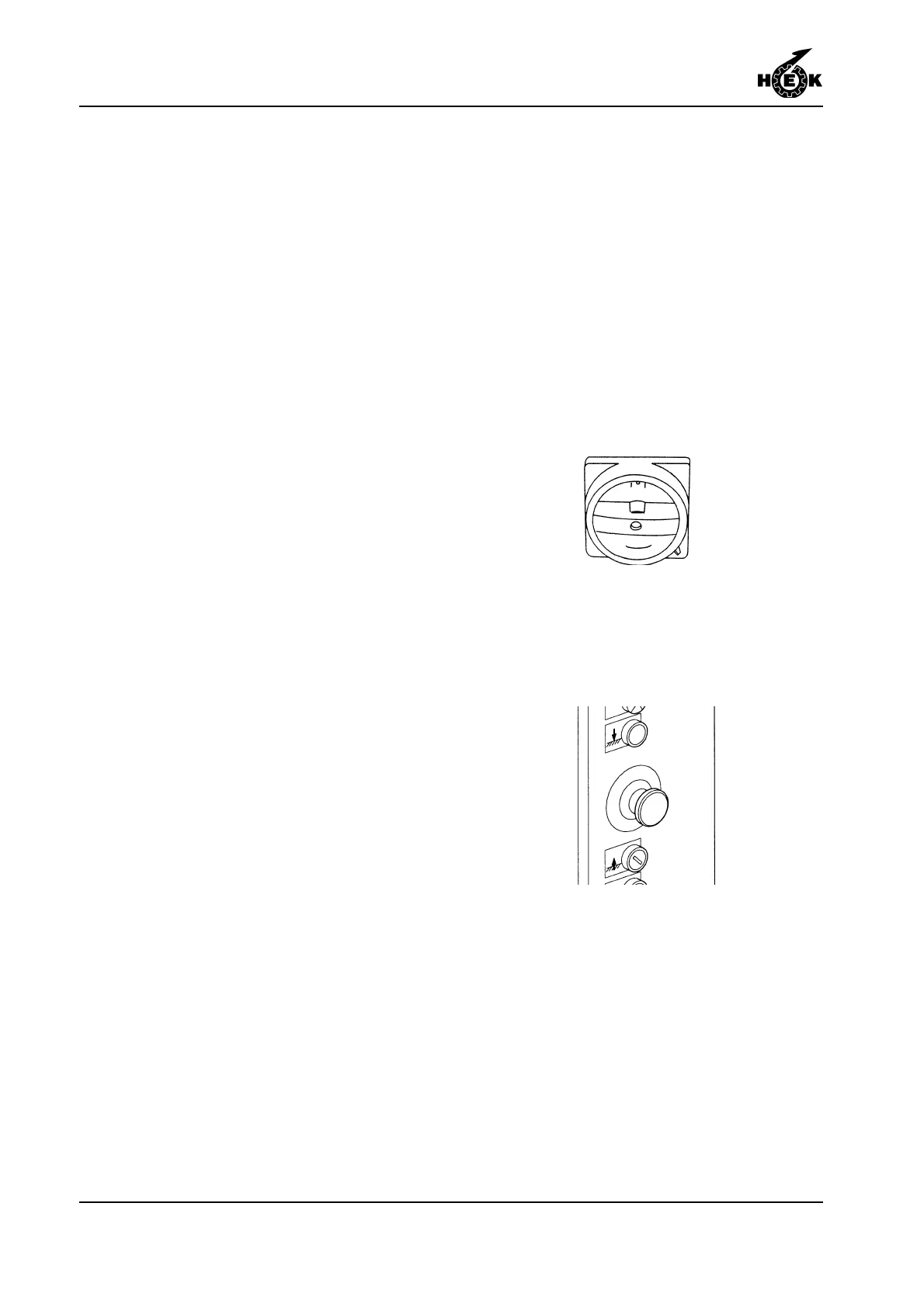
Fig.7-1 Main switch
Fig.7-2 Emergency push-button
- protective covers (presence and
securing)
- securing of the platform extension
- operation of the limit switches
- no obstacles in the path of the
platform
- oil leaking from the drive units
- functioning of the motor brakes
(section 7.4).
2. Connect the electrical power supply.
3. Close the gate.
4. Remove the padlock from the main
switch.
5. Place the main switch in position I or
II (the position depends on the
direction of phase rotation of the
power supply)
6. Check that the EMERGENCY push-
button on the control box is switched
off (the push-button must be pulled
out).
7. If the display shows code 02 and the
phaseguard light does not burn, the
main switch must be set in the other
position. The display will show code
00. If the electric safety circuit (gates,
etc.) is closed the blue light on the
control box will burn.