9
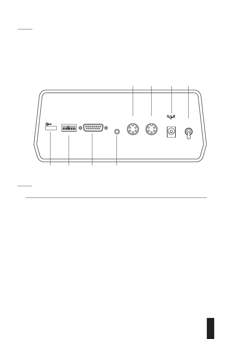
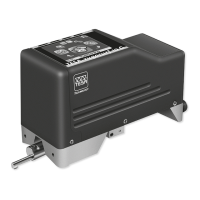
4.3 Rear face
1 ON/OFF switch
2 Mains power
3 Probe input B
4 Probe input A
5 Foot switch input
6 Signal input/output, connector 15-pin/f
7 Configuration switch
8 OPTO-RS input/output
AUTO RANGE
RS
ON
O
FF
18
IN / OUT EXT. P DC 7,3V ON
AB
5678
4 3 2 1
Fig. 2
4.4 Sub-D connector, 15-pin female
N
o
Function
1 Strobe
2 DATA output for 5 to 40 good classes + Scrap and Rework.
3 Clock
4 Classification relay : rework, amber LED.
(Mode TT90-UPC = backward bolt movement and acknowledgment
of data transmission).
5 Classification relay: scrap, red LED.
(Mode TT90-UPC = forward bolt movement and stabilisation).
6 Output current +5 VDC (100mA max.)
7 GND feedback for R-M switch.
8 Analogue masse.
9 Digital masse.
10 Free.
11 Common point: 3 classification relays.
12 Digital masse.
13 Classification relay : good = green LED.
(Mode TT90-UPC = activation of vaccum pump for bolt retraction).
14 R-M switch input.
15 Analogue output, ±2 V or ±10 V, 3mA and 40nF max.