15
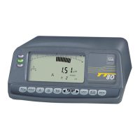
6.7 Memory functions
Each TESATRONIC TT80 and TT90 includes memory functions that provide Users with a
wide number of possibilities when taking measurements.
– Storage of the maximum value. Used when checking external diameters on workpieces
moved under the probe.
– Storage of the minimum value. Used when measuring bore diameters whilst swivelling
a bore gauge with 2-point contact around the culmination point.
– Storage of the difference. Used when determining form and positional errors, especially
axial and radial runout.
– Storage of the mean value. Used when establishing mean values resulting from a value
dispersion due to form and shape errors of the workpiece geometry, for example.
Your instrument has two memories linked to the measuring function. One of both retains
the highest value, and the other the lowest value.
This key allows you to choose one of
the 4 memory functions available whenever
you press it.
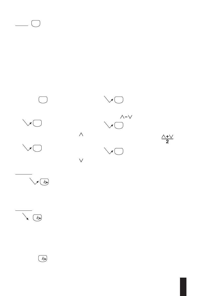
Pressure 1
Displays the maximum value saved in the
memory along with the symbol
Pressure 2
Displays the minimum value saved in the
memory along with the symbol
Pressure 3
Displays the difference between both maxi-
mum and minimum values along with both
symbols
Pressure 4
Displays the mean of both maximum and min-
imum values along with this sign
Pressure 5
Returns to direct displaying.
6.7.1 Memory function in the MEASURE mode
Transfers displayed value to the RS232 output and resets the memories.
Changing chosen memory function causes the memories to be reset to actual value.
6.7.2 Memory function in the HOLD mode
Sets the memories to actual value of the measuring function. Keep this key
pressed down until the measured value is captured. Upon releasing, display is
set to hold along with the memories, and the measured value is sent to the
digital output.
Warning!
Should any correction be made to the measuring mode, display shows dashes only, until
the measured value coming next is captured.
This key along with the input for the foot switch (5, Fig. 2) and both contact relays
7 and 14 (R-M switch) on the 15-pin connector (6, Fig. 2) have the same function.