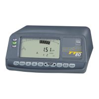
7 MEASUREMENTS
The TT80 and TT90 are fitted with 2 signal inputs. The measurand as displayed can either
result from the two signals or a combination of both.
Each measurement requires the connection of TESA inductive probes or compatible. This
configuration allows static probing (unmoved workpiece) and dynamic probing (moved
workpiece). With moving workpiece, it is advisable to remain within the limits of the per-
missible frequency of the instrument and that of the probes (with regard to this, see the rel-
evant technical specifications).
7.1 Polarity of the measurement signal
A separate signal input A (4, Fig. 2) and B (3, Fig. 2) is assigned to each probe socket. In
a similar way, the connected sensors are defined as «Probe A» and «Probe B».
Each input has its proper function keys and enabling the polarity (±) of the
measurement signal to be selected.
The probe position on the measuring device along with the resulting mathematical func-
tions defines the measuring function that will be used.
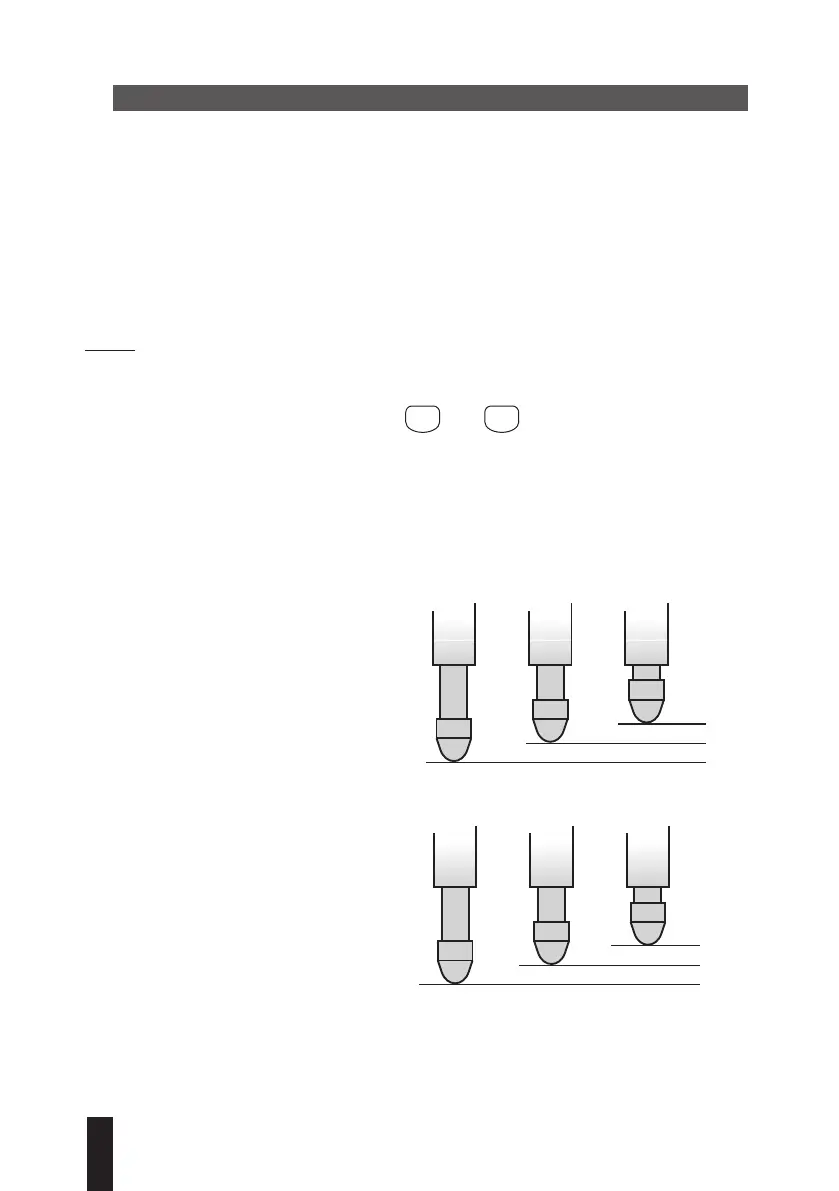
Basic rules
1. A positive polarity +A or +B as the
measuring bolt is being retracted into
the probe induces a positive change of
display.
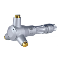
2. A negative polarity -A or -B as the meas-
uring bolt is being retracted into the
probe induces a negative change of dis-
play.
16