Chapter 3. Wiring and Signals
3-8
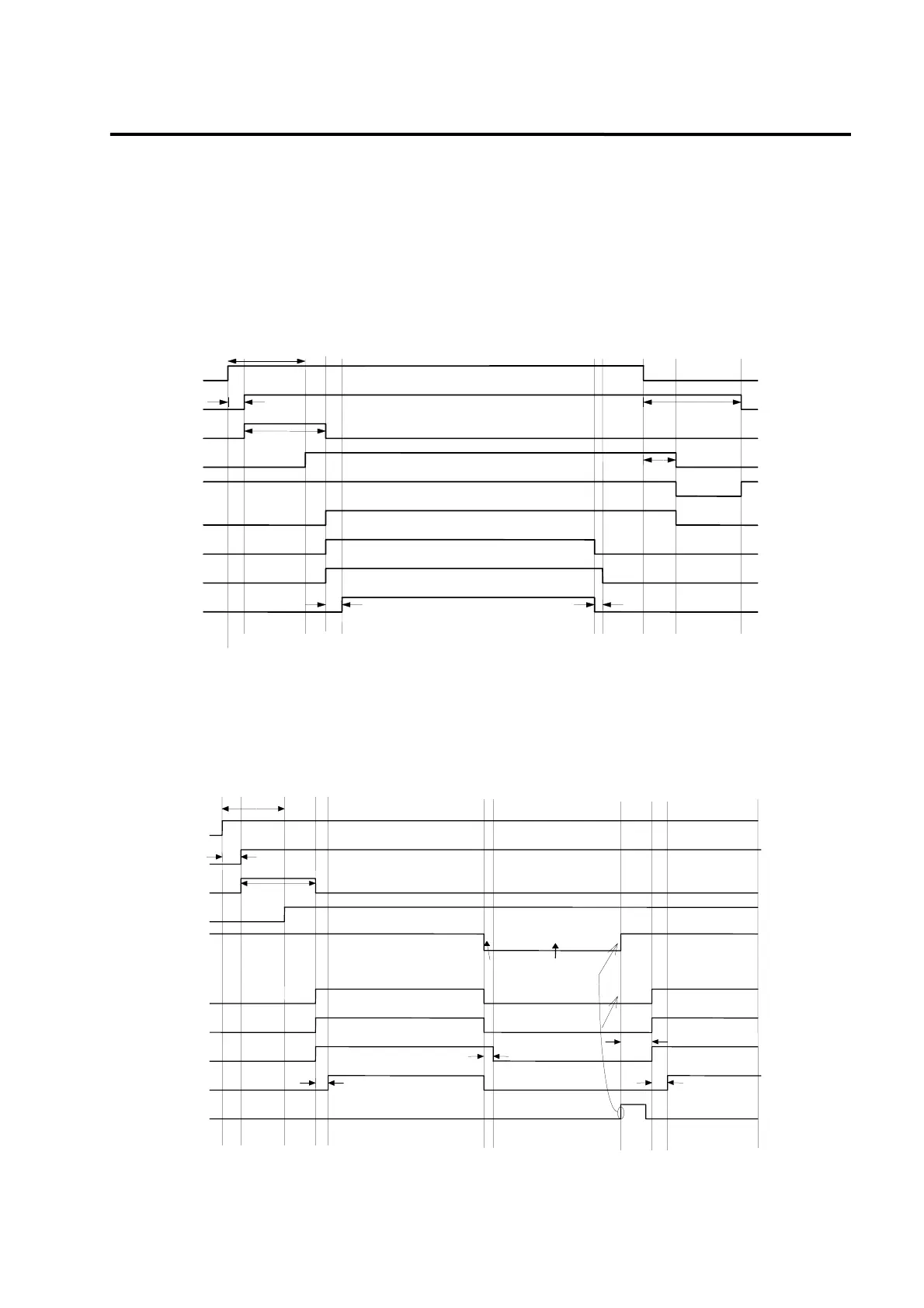
3.3.3 Timing diagram at the time of power connection
In the case of FDA-5001-4, power is supplied to the control circuit if 3-phase power is connected
to the R, S and T terminals. In the case of FDA-5005-10, power is supplied to the control circuit if
single-phase power is connected to the r and t terminals.
Servo becomes RDY after maximum 300 ms, the time required to initialize the inside of the drive
system; and if the servo drive signal is turned on, operation starts 25 ms later.
100ms
Max. 500ms
300ms
Power Good
SVON
DB reset
PWM
(Motor rotation)
Alarm
Nomal ON
Servo RDY
100ms
30ms
1ms
Max. 300ms
Control powerset
(5V)
Control program
initialization
ingle & 3-Phase power
(r,t) & (R,S,T)
3.3.4 Timing diagram at the time of Alarm occurrence
If Alarm occurs on the drive system, PWM is shut off and the motor stops.
(Caution!) Check and remove causes of Alarm and turn off the servo motor drive command
(SVONEN) before resetting Alarm.
100ms
25ms
25ms
1ms
Alarm occurs due to
overload & over current
Control power set
(5V)
ontrol
rogram initialize
Power Good
Alarm
normal ON
Servo RDY
SVON
DB reset
PWM
(Motor rotation)
RESET
Max. 300ms
Max. 500ms
Remove causes
of alarm
Concord
Single & 3-phase power
(r,t) & (R,S,T)
400ms