Chapter 3. Wiring and Signals
3-10
3.4.2 Analog I/O signal
Analog signal is based on 0 [V] (GND terminal) of the control power supply. Connect the GND
terminal of the circuit connected to this signal with the GND terminal of CN1. The analog speed
command input (CN1-27) runs the motor at a speed determined from the [10V Speed [RPM] (P3-
13)] menu of [Speed Mode (P3-13)]. The motor runs at a maximum speed in the forward direction
if +10 [V] is loaded, and in the reverse direction if -10 [V] is loaded. Analog torque limit (CN1-28) is
activated when the analog torque limit function (CN1-14) terminal is turned on, and if the analog
torque limit input is 0 [V] while the torque limit function remains turned on, motor torque does not
occur at all.
If the torque limit input is 10 [V], the function can be used up to the torque set at [10V Torque P5-
02]. As the torque limit command input uses the absolute value of voltage, operation during 10 [V]
is the same as in the case of -10 [V]. If the analog torque limit function is not selected, the function
can be used up to the torque set at [TRQ LMT (+) (P2-05)], [TRQ LMT (-) (P2-06)]. To wire analog
signals, connect GND wire with the signal wire by twisting them using twist pair wire in order to
minimize noise. Functions of each analog signal are as follows.
Pin Name SPDIN ( 27 ) TRQIN ( 28 ) MONIT1 ( 3 ) MONIT2 ( 2 )
Signal
function
Speed command
*
1
Speed limit
*
2
-10∼+10 [V] input
Torque limit
*
1,
*
3
Torque command
*
2
-10∼+10 [V] input
Monitor output 1
-4∼+4 [V] output
Monitor output 2
-4∼+4 [V] output
*1: Effective in speed control mode *2: Effective in speed torque mode *3: Effective in position control mode
Analog signal is based on GND signal, and produces ±12 [V] power just in case speed
commands, speed limits, torque limits and torque commands are applied through the use of
variable resistance. The output capacity of this power supply is 30 [mA] at maximum. Do not
exceed the maximum capacity. The power supply pin array is shown on the following table.
Pin Name + 12 V ( 35 ) - 12 V ( 37 ) GND (1,8,26,33,34,36)
Signal function + 12 [ V ] - 12 [ V ] 0 [ V ]
GND
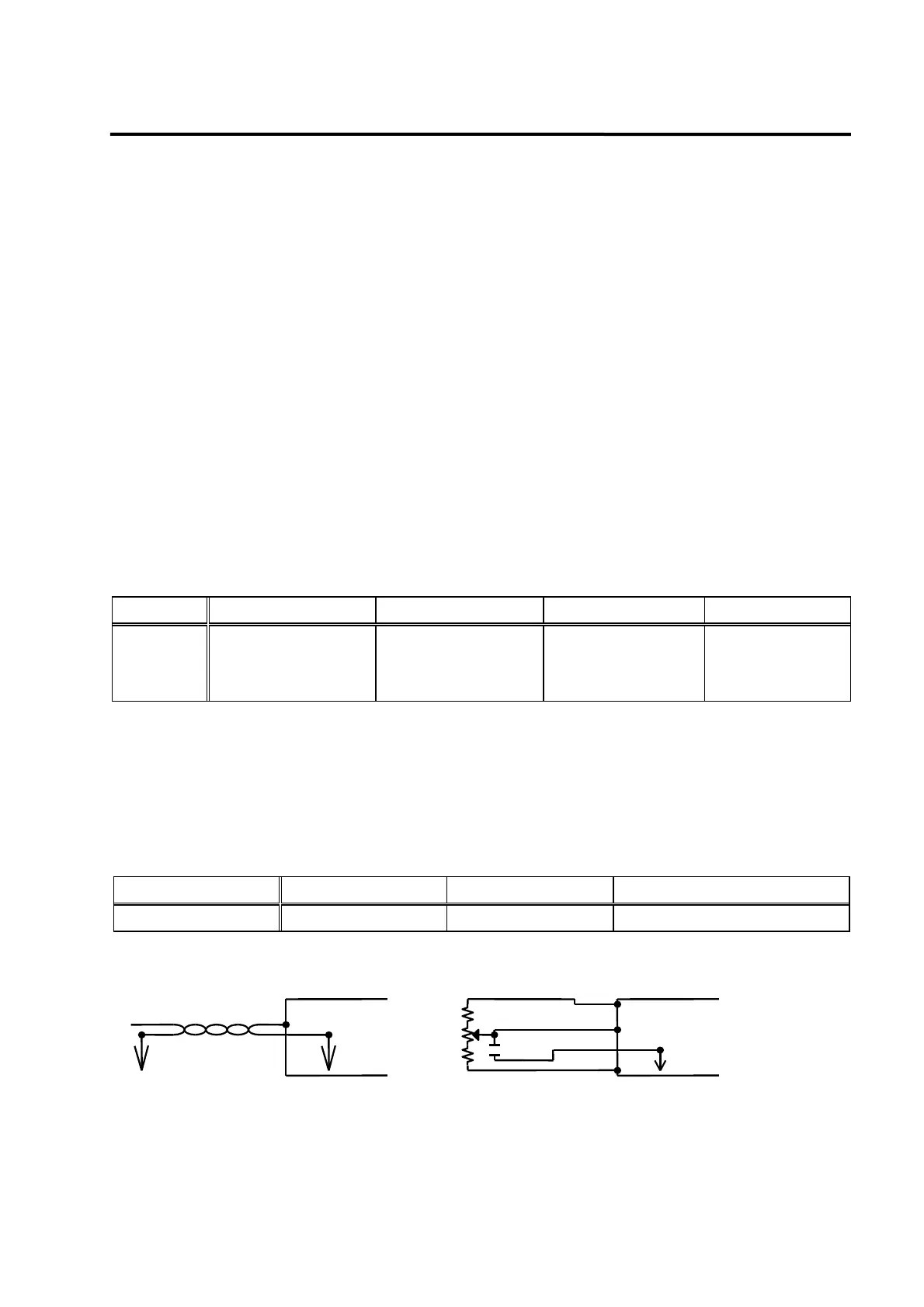
[Analog signal connection]
Driver
SPDIN
TWIST
PAIR
eed command
1/2W 220
2K
1/2W 220
104
GND
Driver
SPDIN
[Using the internal power for the analog command]
-12V
+12V