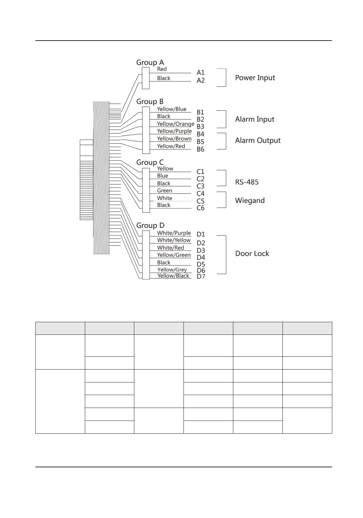
Figure 4-1 Terminal Diagram
The
descripons of the terminals are as follows:
Table 4-1 Terminal Descripons
Group No. Funcon Color Name Descripon
Group A A1 Power Input Red +12 V 12 VDC Power
Supply
A2 Black GND Ground
Group B B1 Alarm Input Yellow/Blue IN1 Alarm Input 1
B2 Black GND Ground
B3 Yellow/Orange IN2 Alarm Input 2
B4 Alarm Output Yellow/Purple NC Alarm Output
Wiring
B5 Yellow/Brown COM
DS-K1T981 Series Access Control Terminal User Manual
19
 Loading...