F3 AIO 8/4 01 4 Start-Up
HI 800 161 E Rev. 1.01 Page 35 of 54
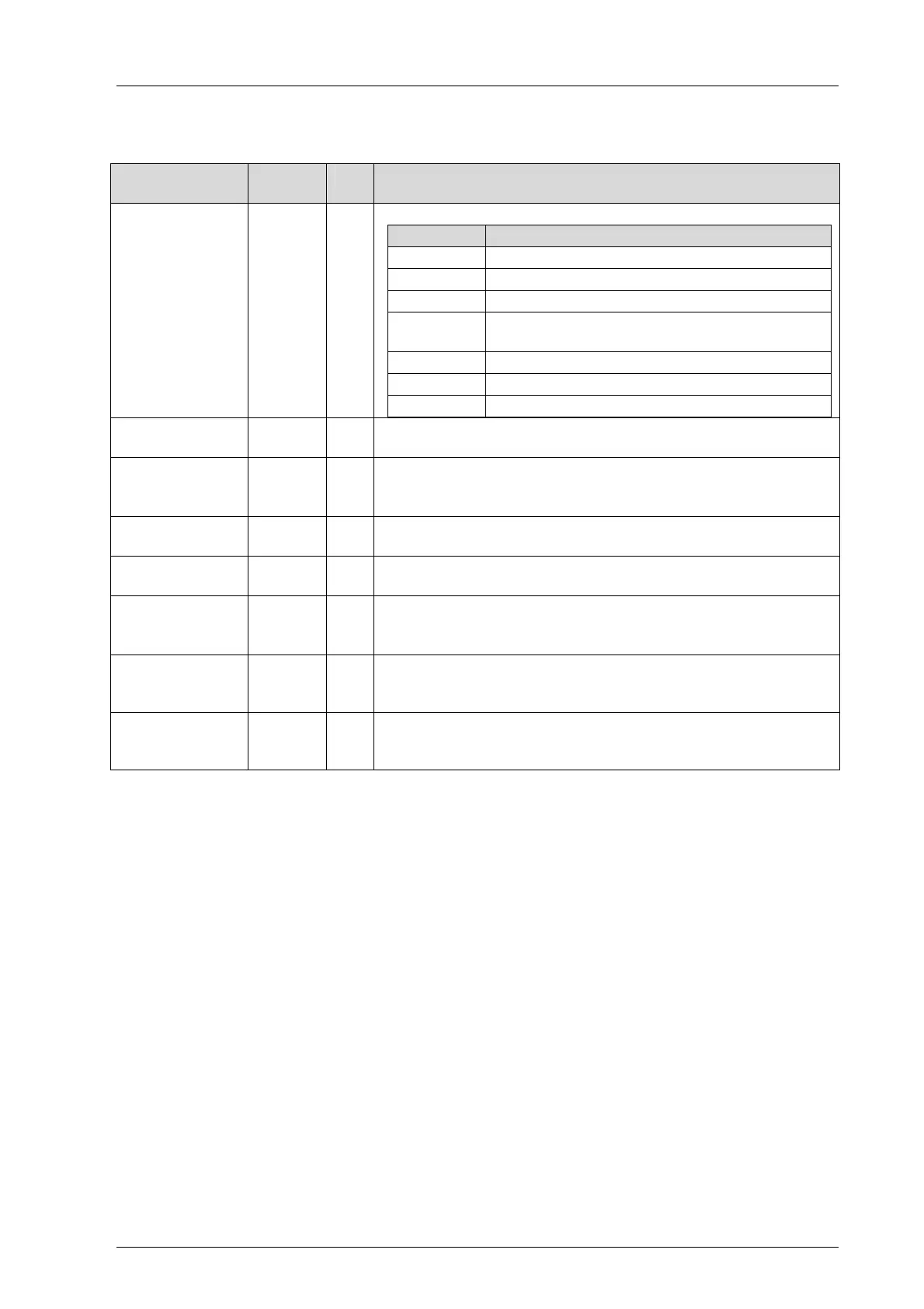
4.3.2.2 AI 8: Channels Tab
The AI 8: Channels tab contains the following system variables.
System
parameter
Data
type
R/W Description
-> Error Code
[BYTE]
BYTE R Error codes for the analog input channels
Coding Description
0x01 Fault in the analog input module
0x02 Out of the defined limit values.
0x04 A/D converter faulty, measured values invalid
0x08
Measured value out of the safety-related
accuracy
0x10 Measured value overflow
0x20 Channel not operating
0x40 Address error of both A/D converters
-> Value [INT] INT R
Analog value for each channel [INT] from 0...+2000 (0...+10 V).
The validity depends on AI.Error Code.
Channel Used
[BOOL] ->
BOOL W Channel configuration:
1 = operating
0 = not operating
Limit Value LOW
[INT] ->
INT W Voltage range upper limit for low level -> Underflow [BOOL]
Limit Value HIGH
[INT] ->
INT W Voltage range low limit for high level -> Overflow [BOOL]
Transmitter
Used [BOOL] ->
BOOL W AI channel used with transmitter supply:
1 = used
0 = not used
-> Underflow
[BOOL]
BOOL R
Underflow -> Value [INT] in accordance with Limit Value LOW
[INT] ->
The validity depends on AI.Error Code
-> Overflow
[BOOL]
BOOL R
Overflow -> Value [INT] in accordance with Limit Value HIGH
[INT] ->
The validity depends on AI.Error Code
Table 27: SILworX - System Parameters for the Analog Inputs, AI 8: Channels Tab

 Loading...


