3 Product Description F3 AIO 8/4 01
Page 14 of 54 HI 800 161 E Rev. 1.01
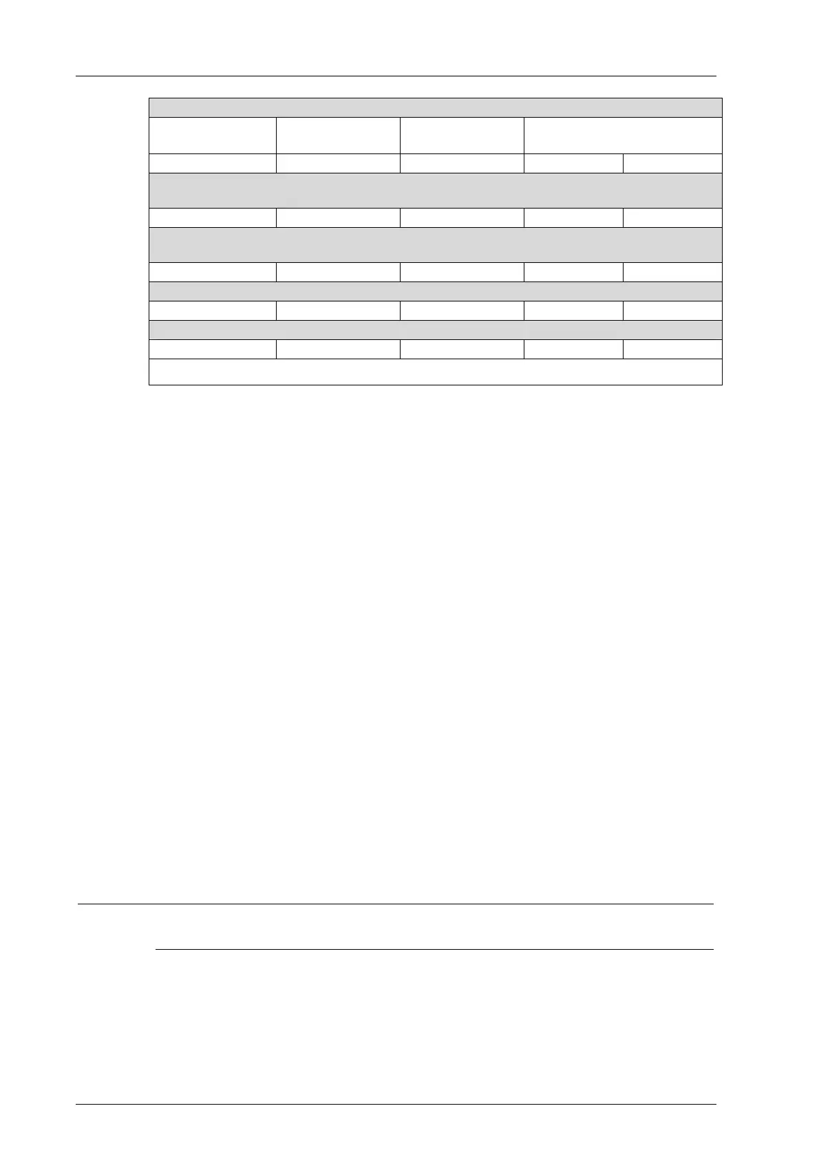
Measured values for voltage on AI with line monitoring of DO
Voltage drop
R
series resistor
Voltage drop
R
solenoid valve
Voltage drop
R
Shunt
Values for AI
(with FSx000 resolution)
FS1000 FS2000
Output DO False or 0
(output DO is deactivated; de-energized state)
25.08 V 1.15 V 0.15 V 14 28
Output DO True or 1
(output DO activated)
- 21 V 3 V 300 600
Break in the field wiring
- - 0 V 0 0
Short-circuit in the field wiring or actuator
- 0 V 26.8 V 1000
1)
2000
1)
1)
maximum resolution of the analog inputs AI with voltage limited to 12 V by Z-diode
Table 7: Voltage Values with Line Monitoring of DO
Illustration of Figure 1 and Table 7
1. Open-circuit:
The supply voltage of the series resistor (transmitter voltage) fluctuates within a tolerance
range, see Specifications in
Table 18. For this reason, the voltage drops on the resistors
can change slightly. Within the fluctuation range, a measurable voltage drop is definitely still
detected on shunt R
shunt
.
The series resistor was dimensioned such that when DO = FALSE, the voltage drop on the
solenoid valve is as low as possible (valve is slightly warmed up) and the voltage drop on
the shunt is still measurable.
The shunt R
shunt
was measured with dependence on the solenoid valve resistance such that
if the output DO is activated (DO = TRUE), the voltage drop on the solenoid valve is higher
than the switching threshold of the solenoid valve, i.e., the coil of the solenoid valve is
energized.
Additionally, the shunt R
Shunt
is designed such that with any switching state of the output
DO (TRUE or FALSE), a measurable voltage drop results (values for AI > 10, see
Table 7).
On the other hand, if field wiring breakage occurs within the red-colored area, voltage drops
are no longer present on the shunt.
An open-circuit within the red-colored area (see
Figure 1) can be monitored through the
voltage drop on the shunt R
shunt
, i.e., the input value of AI, see Table 7.
To allow line monitoring, the value of AI must be evaluated in the logic of the user program.
i
Connect the series resistor R
series resistor
and the shunt R
shunt
directly to the terminals of the
controller or remote I/O to maximize the monitored line area.

 Loading...


