4 Start-Up F3 AIO 8/4 01
Page 30 of 54 HI 800 161 E Rev. 1.01
4 Start-Up
To start up the remote I/O, it must be mounted, connected and configured in the
programming tool.
4.1 Installation and Mounting
The remote I/O is mounted on a 35 mm DIN rail (DIN) or a mounting plate in case of the
F3 AIO 8/4 012 (subsea / -20 °C).
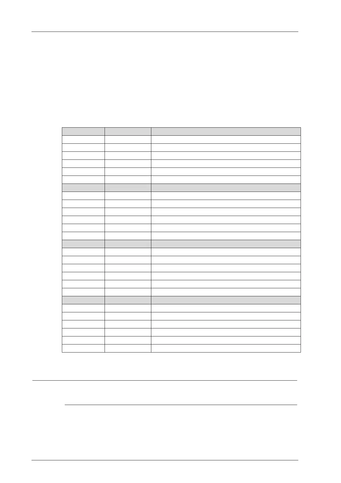
4.1.1 Connecting the Analog Inputs
Use the following terminals to connect the analog inputs:
Terminal Designation Function (analog inputs AI)
1 S1 Transmitter supply 1
2 I1+ Analog input 1
3 I1- Ground
4 S2 Transmitter supply 2
5 I2+ Analog input 2
6 I2- Ground
Terminal Designation Function (analog inputs AI)
7 S3 Transmitter supply 3
8 I3+ Analog input 3
9 I3- Ground
10 S4 Transmitter supply 4
11 I4+ Analog input 4
12 I4- Ground
Terminal Designation Function (analog inputs AI)
13 S5 Transmitter supply 5
14 I5+ Analog input 5
15 I5- Ground
16 S6 Transmitter supply 6
17 I6+ Analog input 6
18 I6- Ground
Terminal Designation Function (analog inputs AI)
19 S7 Transmitter supply 7
20 I7+ Analog input 7
21 I7- Ground
22 S8 Transmitter supply 8
23 I8+ Analog input 8
24 I8- Ground
Table 23: Terminal Assignment for the Analog Inputs
i
Only shielded cables with a maximum length of 300 m should be connected to the inputs.
The shielding must be connected to the remote I/O and the sensor housing and earthed on
one end to the remote I/O side to form a Faraday cage.

 Loading...


