F3 AIO 8/4 01 3 Product Description
HI 800 161 E Rev. 1.01 Page 11 of 54
3 Product Description
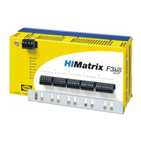
The safety-related F3 AIO 8/4 01 remote I/O is a compact system located in a metal
enclosure with 8 analog inputs and 4 analog outputs.
The remote I/O is available in three model variants for SILworX and three model variants
for ELOP II Factory, see Chapter
3.3. All variants are described in this manual.
The remote I/O serves as extension of the I/O level of HIMax and HIMatrix controllers, and
is connected to them via safeethernet. The remote I/O itself is not able to run a user
program.
The HIMatrix remote I/Os are not multi-master capable.
The remote I/O is suitable for mounting in Ex-zone 2, see Chapter
4.1.3.
The device has been certified by the TÜV for safety-related applications up to SIL 3 (IEC
61508, IEC 61511 and IEC 62061), Cat. 4 (EN 954-1) and PL e (EN ISO 13849-1). Further
safety standards, application standards and test standards are specified in the certificate
available on the HIMA website.
3.1 Safety Function
The remote I/O is equipped with safety-related analog inputs. The input values on the
inputs are safely transmitted to the connected controller via safeethernet. The outputs are
safely assigned their values by the connected controller via safeethernet.
3.1.1 Safety-Related Analog Inputs
The remote I/O is equipped with 8 analog inputs with transmitter supplies for the unipolar
measurement of voltages, referenced to L-.
The remote I/O is intended to measure the voltage on the inputs. To measure the current
on the inputs, connect a resistor of up to 500 in parallel to each input.
Only shielded cables with a length of a maximum of 300 m must be connected to the
analog inputs. Each analog input must be connected to a twisted pair of wires. The
shielding must be connected to the remote I/O and the sensor housing and earthed of one
end to the remote I/O side to form a Faraday cage.
i
Unused input channels must each be short-circuited to the ground (L-).
The following input values are available:
Input
channels
Polarity
Current
Voltage
Range of values
in the application
Safety-related
accuracy
8 unipolar 0...+10 V 0...2000 2%
8 unipolar 0/4...20 mA
0...1000
1)
0…2000
2)
2%
2%
1)
with external Z 7301 shunt adapter, see Chapter 4.1.1.1
2)
with external Z 7302 shunt adapter, see Chapter 4.1.1.1
Table 4: Input Values for the Analog Inputs

 Loading...