8
────────────────────────────────────────────────────
2.2 Connecting the Test Leads
────────────────────────────────────────────────────
2.2.1 Establishing the Connections
CAUTION
Themaximumvoltagewhichcanbeappliedtothetestterminalsofthe
3522-50 unit is 10 V DC. If a DC voltage greater than this is applied
continuously, the unit may be damaged. (For how to apply a DC bias
voltage, refer to Section 5.7, "Supplying DC Bias")
Using a low frequency to measure capacitors with a particular polarity (for
example, electrolytic capacitors) results in a reverse bias being applied. In
some cases this could damage or destroy the capacitor, and therefore a
DC bias should always be applied while making the measurements. Also
be sure that the positive terminal of the capacitor is connected to the H
CUR
terminal on this unit.
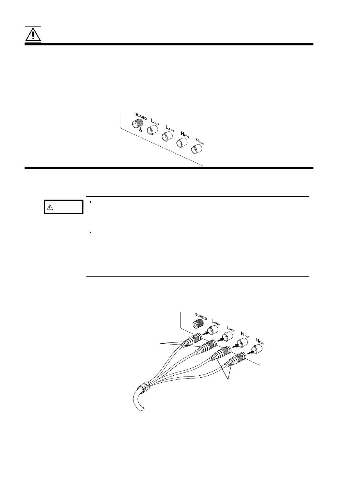
Red
Black
2.2 Connecting the Test Leads
The 3522-50 has five test terminals: H
CUR
terminal (to which the test signal
is supplied); H
POT
terminal (detected voltage high terminal); L
POT
terminal
(detected voltage low terminal); L
CUR
terminal (test current detected
terminal), and GUARD terminal (connected to the chassis of the unit).
If using a test lead set supplied by HIOKI, connect the red leads to the H
CUR
terminal and to the H
POT
terminal, and connect the black leads to the L
CUR
terminal and to the L
POT
terminal.
The unit is designed and adjusted for 75 Ω coaxial cable test leads. It is
best to use HIOKI test leads.