K
Karen YoungAug 17, 2025
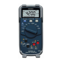
How to fix a Hioki Multimeter when nothing appears on the display?
- ZzhallAug 17, 2025
If nothing appears on the Hioki Multimeter display, or the display disappears quickly, first, check if the batteries are exhausted and replace them if needed. Second, ensure the auto power save function is not activated and adjust its settings if necessary.