Nr. Label Function
1 EXT 2 Extension interface EXT 2
2 LED Indicators LED Indicators for the different interfaces
3 USB USB 2.0 host port, can be used for software/configuration updates.
4 Reset Reboot and factory reset button
5 ETH 1- 4 FastEthernet switch ports, can be used as LAN or WAN interface.
6 MOB 2/WLAN 2 SMA female connectors for MIMO LTE 2 antenna or MIMO WLAN 2 an-
tenna. A6 is the main port, A7 is the auxiliary port.
7 MOB 1 SMA female connectors for LTE/UMTS antennas. A1 is the main, A2 the
auxiliary port
8 BT SMA female connector (A3) for Bluetooth.
9 WLAN 1 SMA female connectors MIMO WLAN 1 antenna. A3 is the main port, A4
is the auxiliary port.
10 GNSS SMA female connector for GNSS antenna
11 EXT 1 Extension interface EXT 1
12 DO1 Digital Output
13 DI1 Digital Input
14 RS-232 RS-232 port
15 PWR Power supply 12-24 VDC.
16 SIM Slots for 2 Micro SIMs (3FF)
Table 4.2.: NB1601 Interfaces
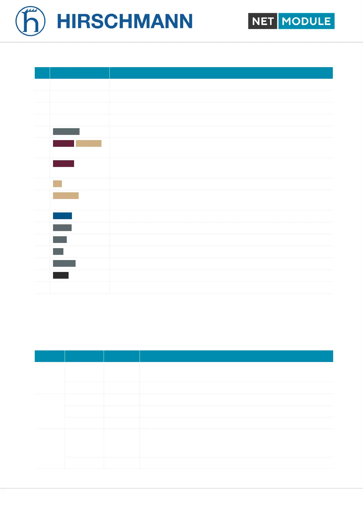
4.4.2. Default LED Indicators
The following table describes the default NB1601 status indicators.
Label Color State Function
STAT lg Blinking Device busy; device is in startup, software- or configuration up-
date.
lg On The device is ready.
WAN lg On The hotlink connection is up.
lg Blinking The hotlink connection is establishing or changing the interface.
m Off The hotlink is disabled.
LAN lg On A WLAN access-point or ETH LAN-connection is up.
ETH: enabled as LAN and link status is up
WLAN: WLAN enabled and configured as access-point.
m Off No WLAN or ETH LAN-connection is up.
NB1601 21 User Manual for NRSW version 4.8.0.103