IEC10000231 V1 EN-US
Figure 17: An example of analog input configuration via PCM600
4.3.2 Configuration of output signals
M12022-93 v4
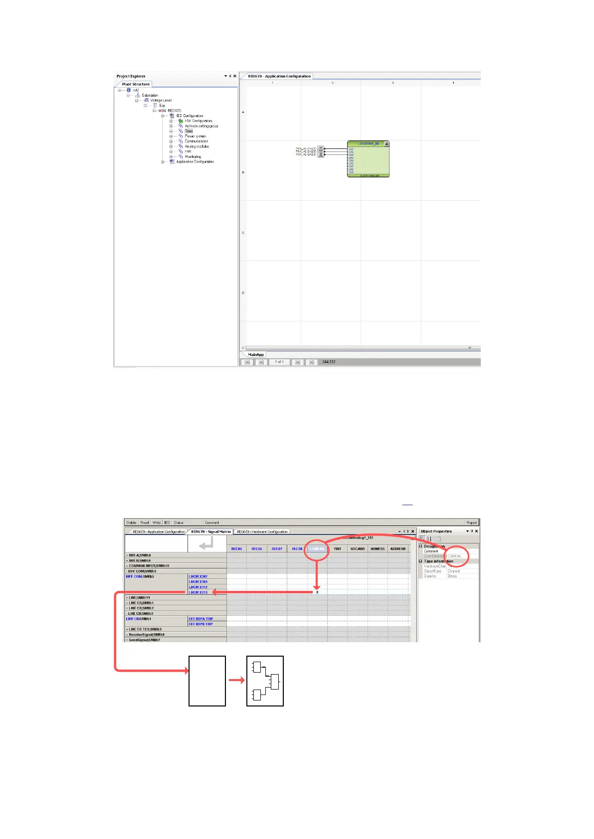
There are a number of signals available from the LDCM that can be connected to the virtual binary
inputs (SMBI) and used internally in the configuration. The signals appear only in the Signal Matrix
Tool (SMT) where they can be mapped to the desired virtual input.
The signal name is found in the Object Properties window by clicking on the input signal number in
SMT. Connect the signals to the virtual inputs as desired (see Figure
18
IEC06000638 V2 EN-US
Figure 18: Example of LDCM signals in SMTl
Section 4 1MRK505382-UEN Rev. K
Analog and binary signal transfer for line differential protection
24 Communication set-up, 670/650 series
Application Guide
© 2017 - 2023 Hitachi Energy. All rights reserved
 Loading...


