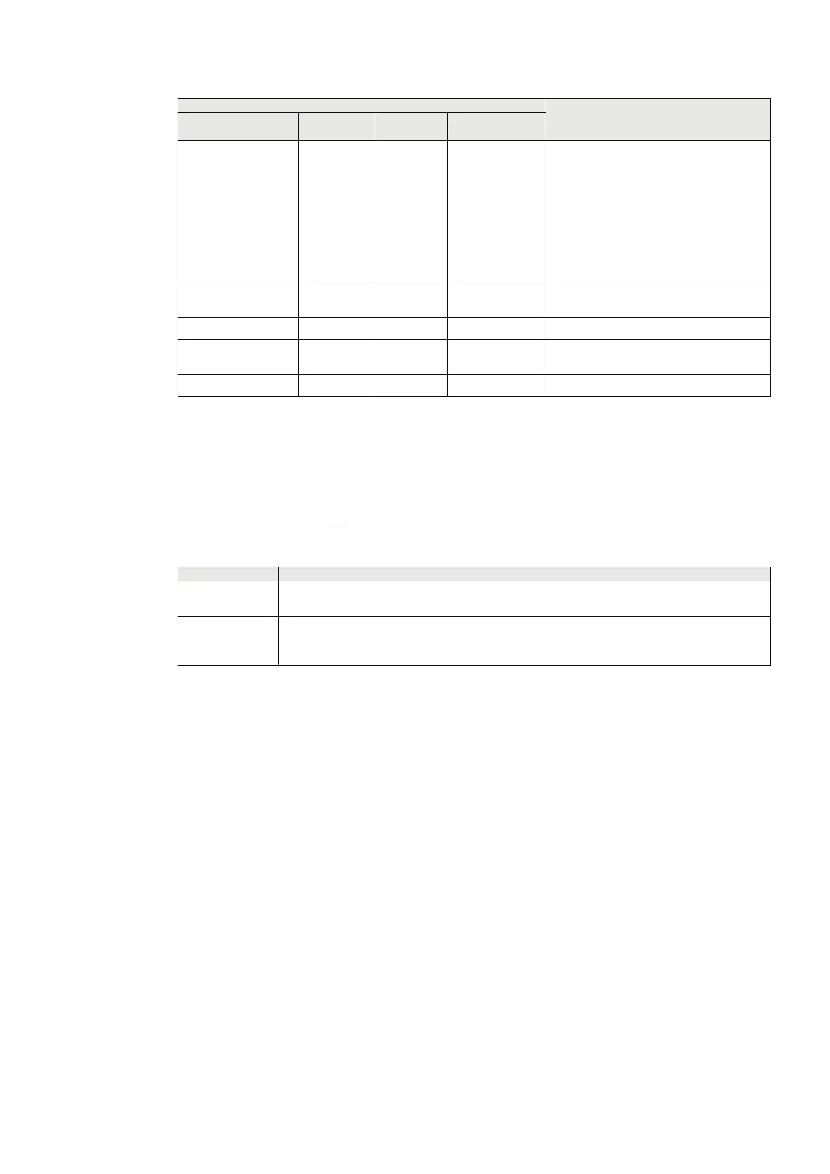
LHMI info Description
Setting/signal Normal
(example)
Faulty
(example)
Specification
NOCARR 0 1 Status No carrier is detected in the incoming
message. Group signal - Logical OR for:
• LINK_LOST (no input data stream at
the optical receiver)
• SYNC_LOST (clock synchronization
is lost)
• C37 ERROR (error at the C37.94
fiberoptic receiver: faulty format)
NOMESS 0 1 Status No start and stop flags in the incoming
message
LNGTHERR 0 1 Status Incorrect length for the incoming message
YBIT 0 1 Status Detected error in an incoming message at
the remote end
LOWLEVEL 0 1 Status Low signal level in the receive link
1) Approximately 75% RXD is typical if, for example, two master clocks are present in the telecommunication network.
5.7.2 Detecting communication faults on transceiver 21-216
GUID-A0B9019C-F470-49AA-AD36-56B1FCCB5E01 v1
Some LED indicators on the transceiver 21–216 front panel can be used for communication fault
tracing as shown in Table
31.
Table 31: LED indicators used for detecting communication faults
LED name
Fault indication
RA Remote Alarm. Red LED indicates that the remote unit has detected a fault condition, and has
set the Yellow Alarm bit in the C37.94 protocol.
LA Local Alarm. Red LED indicates that transceiver 21-206 has detected a fault condition in the
C37.94 protocol (LOS = Loss Of Signal). The Yellow Alarm bit is set in the outgoing C37.94
protocol.
If the line differential protection IED shows a communication fail alarm but RA or LA LED is not lit on
transceiver 21-216, communication interruption stems from the telecommunication network.
5.7.3 Detecting communication faults on transceiver 21-219
GUID-4652FF2A-E9C1-4EEF-A764-8A9B413E9FC3 v1
Some LED indicators on the transceiver 21–219 front panel can be used for communication fault
tracing as shown in Table
1MRK505382-UEN Rev. K Section 5
Communication set-up
Communication set-up, 670/650 series 89
Application Guide
© 2017 - 2023 Hitachi Energy. All rights reserved
 Loading...


