GUID-E8E1B062-7E32-4850-A5D1-6EDBC82154D4 v1
IEC10000071 V1 EN-US
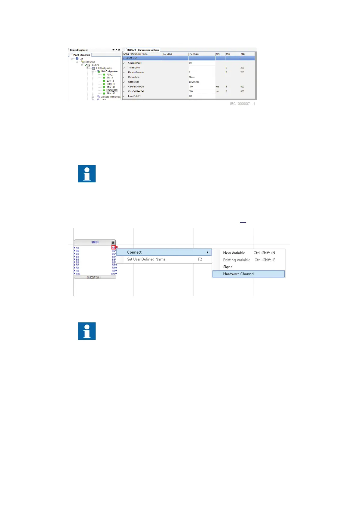
Figure 46: Setting example with one communication channel for binary transfer
4.8.2 Configuration of binary inputs and outputs
GUID-89D944D1-DD6C-4666-8AA6-38FE5F366095 v1
GUID-0918C53D-F755-4FA1-BB3C-F672AFC6A7D2 v1
Signals are available in the Signal Matrix Tool (SMT) and as hardware channels in the
Application Configuration Tool (ACT).
4.8.2.1 Configuration of binary inputs and outputs via ACT
GUID-7102E264-F540-434C-96BA-47E72DA665B2 v1
LDCM hardware channels can be connected via ACT by right-clicking on the chosen connection
point, and then selecting Connect /Hardware Channel (see Figure
47).
IEC10000241 V1 EN-US
Figure 47: Configuration of binary inputs and outputs via ACT
If an installed LDCM is not used, it should be removed or set to binary mode without any
connections, or the ChannelMode parameter should be set to Blocked. Otherwise parallel
LDCMs may get blocked.
The following can be done in the Hardware Channel Allocation dialog:
• Hardware Module selection
• Hardware Channel selection
• User Defined Name for the channel
Section 4 1MRK505382-UEN Rev. K
Analog and binary signal transfer for line differential protection
46 Communication set-up, 670/650 series
Application Guide
© 2017 - 2023 Hitachi Energy. All rights reserved
 Loading...


