IEC07000254 V1 EN-US
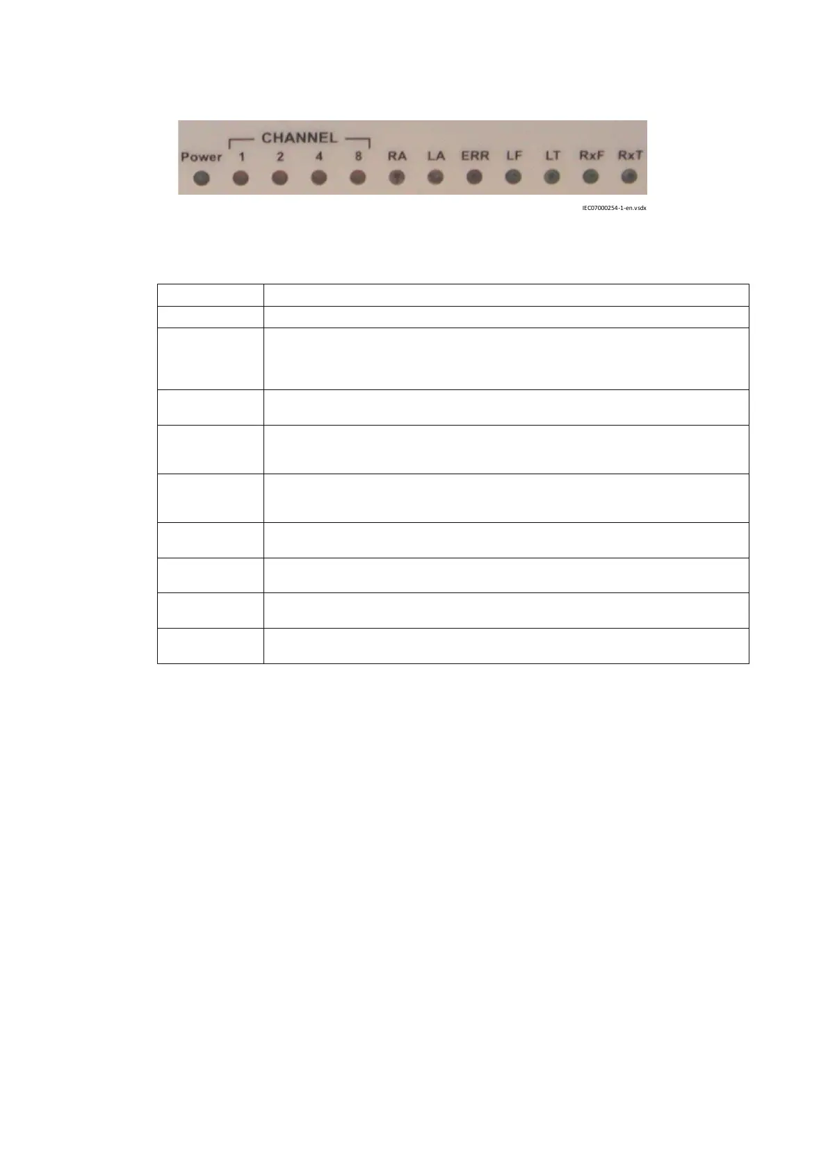
Figure 74: Front panel LEDs
LED name LED function
Power Green LED is lit when power is connected to the unit.
CHANNEL Yellow LEDs represent the channel chosen by jumpers at installation. The channel is calculated
by summing up lit CHANNEL LEDs. For example, if CHANNEL 1 and CHANNEL 2 are lit (1+2 =
3), channel 3 is chosen. This means that data to/from the G.703 co-directional port is sent and
received via C37.94 protocol on the fiber.
RA Remote Alarm. Red LED indicates that the remote unit has detected a fault condition, and has
set the Yellow Alarm bit in the C37.94 protocol.
LA Local Alarm. Red LED indicates that transceiver 21-216 has detected a fault condition in the
C37.94 protocol (LOS = Loss Of Signal). The Yellow Alarm bit is set in the outgoing C37.94
protocol.
ERR Error. Red LED indicates that transceiver 21-216 has detected an internal error or that a non-
allowed setting of jumpers exists. The ERR led also lits when a non-used channel is selected or
if both codirectional and fiber clocks are selected.
LF Link Fibre. Green LED indicates that transceiver 21-216 is receiving the correct C37.94 frames
(no LOS).
LT Link Twisted pair. Green LED indicates that transceiver 21-216 is receiving the G.703 codir
protocol.
RxF Receive data on Fibre. Green LED indicates that transceiver 21-216 is receiving data in C37.94
format.
RxT Receive data on Twister pair. Green LED indicates that transceiver 21-216 is receiving data
G.703 codir protocol.
5.5.5 Service settings
GUID-4945ED6C-5CE7-4C32-8911-0D7057C11B0E v1
5.5.5.1 Service settings for the line differential protection IED
GUID-5C96797C-B5CF-4E81-9DDB-02FF91492A90 v1
Line differential protection IEDs used in the communication set-up are set to operate as slaves
(CommSync = Slave).
Section 5 1MRK505382-UEN Rev. K
Communication set-up
76 Communication set-up, 670/650 series
Application Guide
© 2017 - 2023 Hitachi Energy. All rights reserved
 Loading...


