5.6.8 Communication structure for laboratory testing
GUID-EEB88BED-45BA-4C38-BAEE-0DECCB003314 v1
During back-to-back laboratory testing, one transceiver 21-219 must be set as master. This is done
by turning the rotary switch on the transceiver's front panel to position 1 (EXT CLK) (LED 1 is lit and
LEDs 2, 4 and 8 are not lit).
5.7 Communication status and fault tracing
5.7.1 Communication status on the line differential protection IED
GUID-36DB09A7-DFD0-4E5A-9475-6FBF9D1BACB2 v1
Communication status can be monitored on the line differential protection IED's local HMI under
Main menu /Test /Function status /Communication /Remote communication . The information is
also useful for fault tracing purposes.
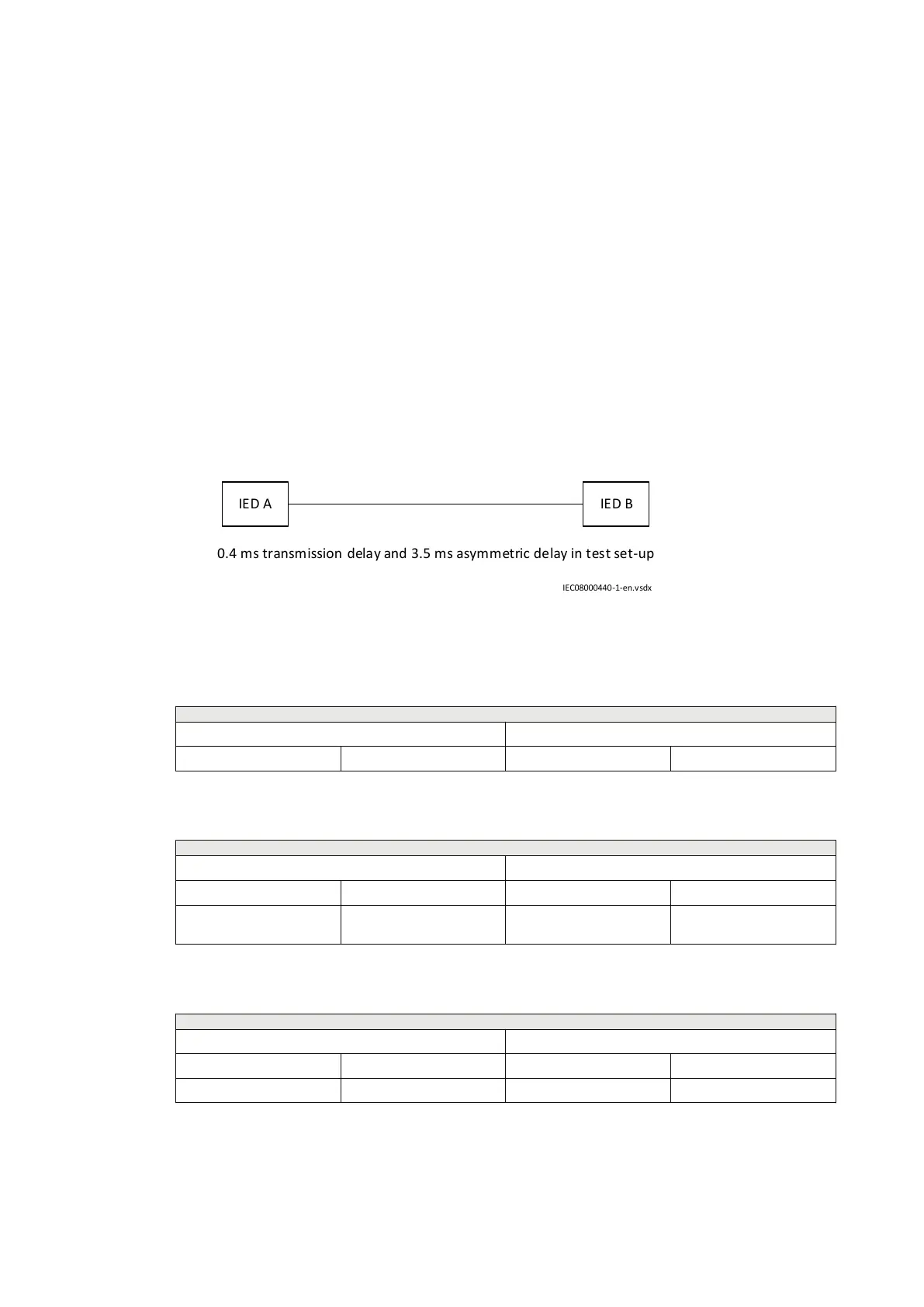
Example of transmission delay and asymmetry information on the local
HMI
IED A IED B
0.4 ms transmission delay and 3.5 ms asymmetric delay in test set-up
IEC08000440-1-en.vsdx
IEC08000440 V1 EN-US
Figure 88: Example test set-up with specified transmission and asymmetric delays
Table 26: Asymmetric delay settings in echo mode
Echo mode
Setting in IED A Setting in IED B
AsymDelay –3.1 ms AsymDelay 3.1 ms
Table 27: Transmission and asymmetric delay values in echo mode
Echo mode
Service values in IED A Service values in IED B
TransmDelay 0.4 ms TransmDelay 3.5 ms
AsymDelay –3.1 ms (same as set
value)
AsymDelay 3.1 ms (same as set value)
Table 28: Actual transmission and asymmetric delay values in GPS mode
GPS mode
Service values in IED A Service values in IED B
TransmDelay 0.4 ms TransmDelay 3.5 ms
AsymDelay –3.1 ms AsymDelay 3.1 ms
Section 5 1MRK505382-UEN Rev. K
Communication set-up
86 Communication set-up, 670/650 series
Application Guide
© 2017 - 2023 Hitachi Energy. All rights reserved
 Loading...


