IEC15000451-2-en.vsdx
IED
IED
A
B
T
T
Protected zone
IEC15000451 V2 EN-US
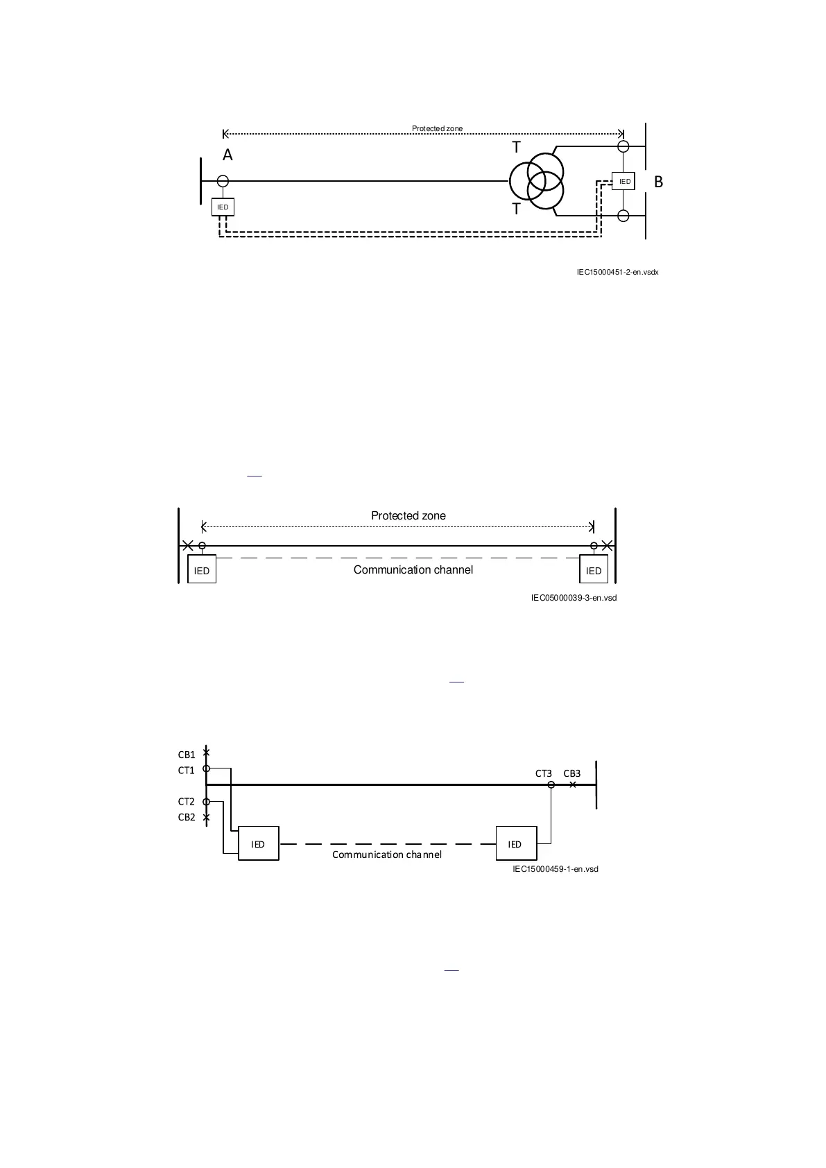
Figure 30: One three–winding transformer in the protected zone
4.6.2 Line differential protection L4CPDIF
4.6.2.1 Possible configurations
GUID-566BF5F0-3E2D-42D8-9D53-BCAFB7F0BEA9 v3
The simplest and most common configuration is the protection of a conventional two-end power line
(see Figure
31). Circuit breakers (CBs) at both ends can be included in the protected zone
depending on their positions relative to the current transformers (CTs).
IEC05000039-3-en.vsd
Protected zone
Communication channel
IED IED
IEC05000039 V3 EN-US
Figure 31: Two-end power line with one CB and one CT group at each end
It is also possible to protect a two-end power line that has two CB and CT groups at one end and one
CB and CT group at the other end (see Figure
32). All currents from the three CTs must be fed
separately to L4CPDIF which processes the measured currents independently from each other.
Summing up the CTs’ secondary currents at the end with two CB and CT groups is not allowed. CBs
at both ends can be included in the protected zone depending on their positions relative to the CTs.
IEC15000459 V1 EN-US
Figure 32: Two-end power line with two CB and CT groups at one end
If there are two CB and CT groups at both ends of a two-end power line, information on currents
must be fed to all four current inputs of both IEDs. Current values at the remote end are obtained via
a communication channel as shown in Figure
33. Summing up the CTs’ secondary currents at the
end with two CB and CT groups is not allowed. CBs at both ends can be included in the protected
zone depending on their positions relative to the CTs.
1MRK505382-UEN Rev. K Section 4
Analog and binary signal transfer for line differential protection
Communication set-up, 670/650 series 31
Application Guide
© 2017 - 2023 Hitachi Energy. All rights reserved
 Loading...


