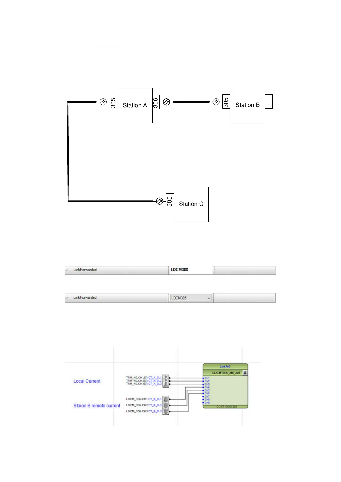
As depicted in Figure 25, three-line ends application with a reduced number of communication links.
The measured current is still exchanged between terminals B and C despite the absence of a
communication link between the two ends. LDCM modules at terminal A handing the current
exchange between terminals B and C.
Setting and configuration for link forward features in the above example:
Station A
Station B
Station C
305
306
305
305
GUID-05C4369C-FFC3-4EDF-B08F-26E1FA3D015F V1 EN-US
Figure 25: Communication links
Set value for LDCM modules:
Station A: Set LDCM 305 to forward the received current from station C to station B.
GUID-1A477E04-A394-4A37-B32E-300951524D10 V1 EN-US
Station A: Set LDCM 306 to forward the received current from station B to station C.
GUID-C3251356-76EF-43A2-A8B6-8D26C845547A V1 EN-US
4.5.1 Application configuration ACT
GUID-AB8ADE46-FA1B-444C-B981-8C099E47C58B v1
Station A: cross connect the received current to LDCMTRN function:
GUID-83DC5973-6028-4D46-9703-6D14F8315CD6 V1 EN-US
Section 4 1MRK505382-UEN Rev. K
Analog and binary signal transfer for line differential protection
28 Communication set-up, 670/650 series
Application Guide
© 2017 - 2023 Hitachi Energy. All rights reserved
 Loading...


