LOCAL REMOTE
< 10 m
IED
Transceiver
21-219
SDH
MUX
IED
Multi-mode
fibre-optic
< 3.5 km
Galvanic
connection
interface
G.703 E1
(2Mbit)
SDH
master
Slaves
Slaves (external clock)
IEC07000156-1-en.vsdx
G.704 (framed etc.)
< 10 m
SDH
MUX
Multi-mode
fibre-optic
< 3.5 km
Galvanic
connection
interface
G.703 E1
(2Mbit)
Transceiver
21-219
IEC07000156 V1 EN-US
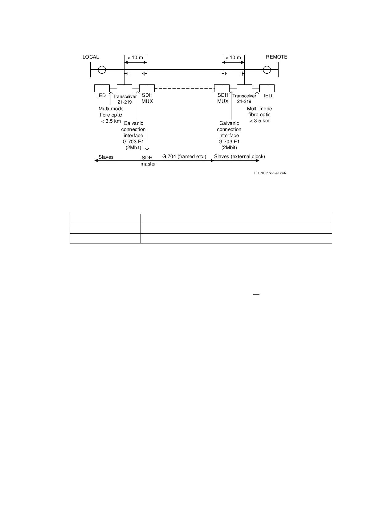
Figure 80: Communication structure with transceiver 21-219 port synchronized from SDH
master clock
IED Terminal used for binary signal transfer
Transceiver 21–219 Optical-to-electrical interface converter
SDH MUX SDH multiplexer
5.6.3 Communication structure with PDH/SDH port synchronized
from transceiver 21-219
GUID-59042A8F-D4CA-41AA-A4B6-17B6A99E199A v1
Setting up a PDH telecommunication network requires that synchronization is provided from an
external source, for example, from one transceiver 21-219 (see Figure
81). The SDH multiplexer
(SDH MUX) is thus set not to interfere with synchronization. This requirement is usually fulfilled by
setting the SDH MUX to transparent mode.
Section 5 1MRK505382-UEN Rev. K
Communication set-up
80 Communication set-up, 670/650 series
Application Guide
© 2017 - 2023 Hitachi Energy. All rights reserved
 Loading...


