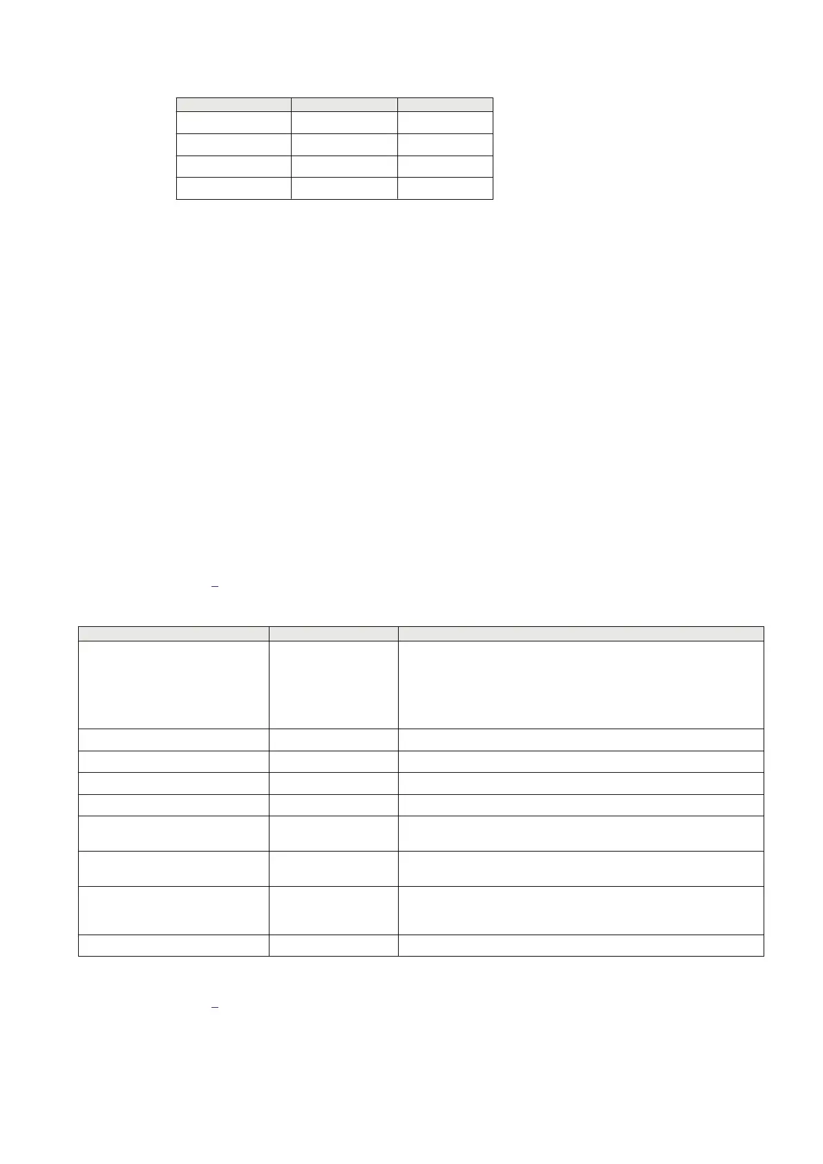
Settings Station A Station B
PDIF L3TCPDIF L3TCPDIF
NoOfUsedCTs 3 3
TraAOnInpCh 2 1
TraBOnInpCh 3 2
Currents from the secondary and tertiary windings of the power transformer are connected to one
line differential protection IED. Currents for each CT group are sent to the IED at station A by the
LDCM. To inform the differential algorithm that currents are coming from the LV sides of the
transformers, TraAOnInpCh must be set to 2 and TraBOnInpCh to 3 (channel1 is reserved for local
measurement). This is to ensure that proper turn ratio and vector group correction is done.
4.7.2 Line differential protection L4CPDIF
4.7.2.1 Setting example with a two-end power line
GUID-4C105C98-F9FE-41B3-A7E0-FC5430EC141A v2
In this example, a two-end 220 kV and 200 km power line is protected using L4CPDIF.
The protected zone is determined by CT positions. One three-phase CT group is placed at one end
of the power line, and another three-phase CT group is placed at the other end. Everything that is
placed between these two CT groups (including CBs) are included in the protected zone.
To apply the exact (voltage-based) method of charging current compensation, the power line's
positive and zero-sequence capacitances must be known. If not known, the approximate method can
be applied instead.
Table
4 shows the power system parameters in this example.
Table 4: Power system parameters
Power line data
Value Remark
Number of three-phase CT groups
(each group represents an
independent source of information
about the current)
2 A two-end power line with one three-phase CT group installed at each
end.
Setting NoOfUsedCTs is used to indicate to L4CPDIF how many current
input channels (2, 3 or 4) with current samples are to be read and
processed.
Source impedance at both ends 4.84 Ω -
Power line length 200 km -
Rated voltage 220 kV -
Line impedance ZL ≈ XL 58.64 Ω -
Total zero sequence line
capacitance, C0
7.751e-9 x 200 7.751e-9 F per 1 km of line
Total positive sequence line
capacitance, C1
12.74e-9 x 200 12.74e-9 F per 1 km of line
Charging current
(measured without charging current
compensation)
92 A Measured at rated voltage as the differential current under normal load.
Rated current 1000 A
Table 5 shows the relevant settings in this example.
1MRK505382-UEN Rev. K Section 4
Analog and binary signal transfer for line differential protection
Communication set-up, 670/650 series 41
Application Guide
© 2017 - 2023 Hitachi Energy. All rights reserved
 Loading...


