Table 5: Relevant settings
Setting Value Remark
IdMin 0.20 20 % of IBase = 1000 A
Must be set above the maximum possible charging current (in this
example set to approximately 2 x of that value).
EndSection1 1.00 100 % of IBase = 1000 A
EndSection2 3.00 300 % of IBase = 1000 A
SlopeSection2 0.50 Slope = 50 %
SlopeSection3 1.00 Slope = 100 %
IdMinHigh 1.00 100 % of IBase = 1000 A
tIdMinHigh 1000 Interval of initial decreased sensitivity in ms.
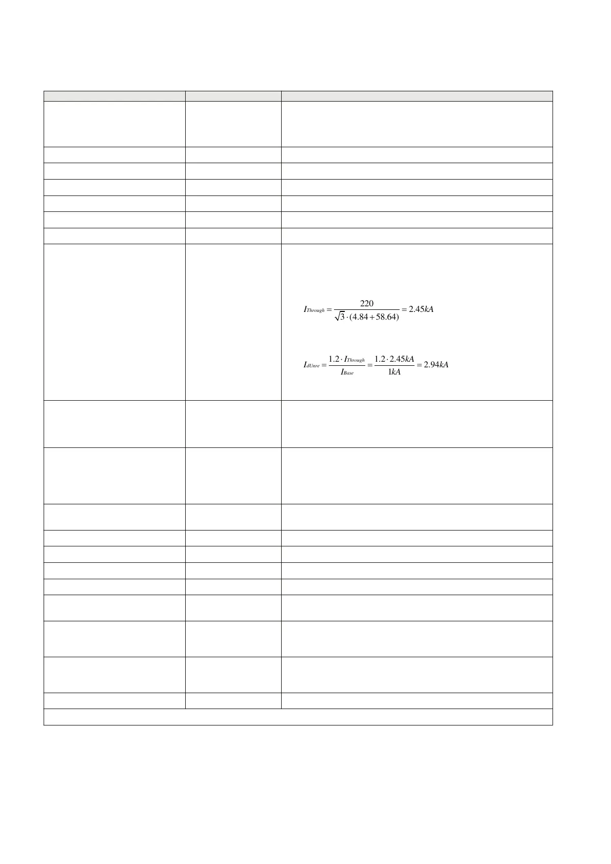
IdUnre 3.00 300 % of IBase = 1000 A
Maximum through fault current calculated based on:
220
2.45
3 (4.84 58.64)
ThroughI kA
IECEQUATION15178 V1 EN-US
1.2 1.2 2.45
2.94
1
Through
dUnre
Base
I kA
I kA
I kA
IECEQUATION15179 V1 EN-US
I2/I1Ratio 0.10 Ratio = 10 %
The value can be set this low because the 2
nd
harmonic block is
ignored if an internal fault is detected.
I5/I1Ratio 0.10 Ratio = 10 %
The value can be set this low because the 5
th
harmonic block is ignored
if an internal fault is detected and no tap transformer exists in the
protected zone.
CCCOpMode 1 The exact method with currents and voltages is used. Line
capacitances must be specified.
VTOnLineGrp1 0 VT is placed on the bus.
VTOnLineGrp2 0 VT is placed on the bus.
C0 7.751e-9 x 200 Total zero sequence capacitance of 220kV on a 200 km power line.
C1 12.74e-9 x 200 Total positive sequence capacitance of 220kV on a 200 km power line.
NoOfLineEnds 2 Number of physical line ends in the protected zone (setting used by
charging current compensation).
NoOfCTSetsGrp1 1 Number of three-phase CT groups at first line end, the currents of which
are connected to input group 1 (setting used by charging current
compensation).
NoOfCTSetsGrp2 1 Number of three-phase CT groups at second line end, the currents of
which are connected to input group 2 (setting used by charging current
compensation).
IBase 1000 Nominal current of the protected power line.
Table continues on next page
Section 4 1MRK505382-UEN Rev. K
Analog and binary signal transfer for line differential protection
42 Communication set-up, 670/650 series
Application Guide
© 2017 - 2023 Hitachi Energy. All rights reserved
 Loading...


