GUID-13B60A3E-CF41-4322-9576-42B5B9152EA5 v1
IEC07000228 V2 EN-US
Figure 19: Typical LDCM application
4.4 Configuration of redundant channels
GUID-99F3FF15-FC76-48DC-959F-FAC1BE0CA4A9 v1
LDCM installation should follow a specific sequence: slot 312, slot 313, slot 322, slot 323, slot 305,
slot 306. 2-4 LDCMs can be included in the installation depending on the availability of IRIG-B and
RS485 modules.
If available, IRIG-B is installed to slot 313 and RS485 to slot 312.
Main and redundant channels are installed in the same base card in slots 305–306, 312–313, and
322–323.
Positions for the main and redundant channels are predefined in the basic configuration, and they
cannot be changed. Only slots 306, 313 and 323 can be set as redundant line differential
communication channels via PCM600.
Signal matrix for the redundant channel must be empty. It is updated automatically when the main
channel is lost.
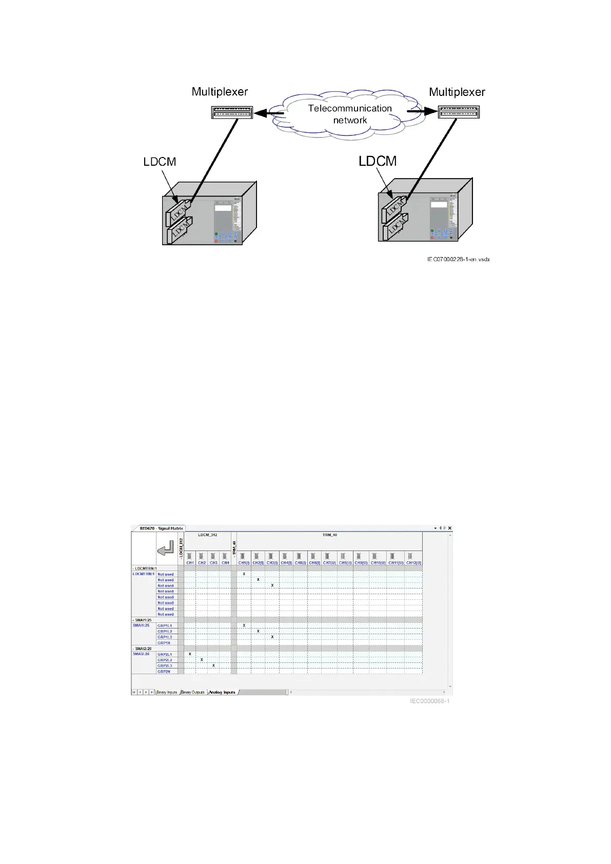
IEC10000068 V1 EN-US
Figure 20: Signal matrix for one main channel
1MRK505382-UEN Rev. K Section 4
Analog and binary signal transfer for line differential protection
Communication set-up, 670/650 series 25
Application Guide
© 2017 - 2023 Hitachi Energy. All rights reserved
 Loading...


