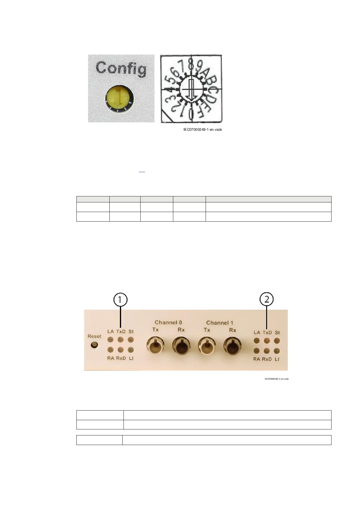
IEC07000249 V1 EN-US
Figure 84: Rotary switch for clock synchronization configuration
Every switch position for clock selection is represented by the four LEDs (1, 2, 4 and 8) on the front
panel as shown in Table
25 (X indicates a lit LED). The LEDs form a corresponding binary-value for
each switch position.
Table 25: LEDs indicating clock synchronization configuration by the rotary switch
LED 1 LED 2 LED 3 LED 4 Function
(0H) External clock selected (slave mode)
X (1H) Internal clock selected (master mode)
5.6.5 Power-up and LED statuses with transceiver 21–219
GUID-52777300-7C19-47E4-BF9B-ED974E050D47 v1
To power up transceiver 21–219, connect the power cord to the transceiver, and then connect the
other end of the cord to mains.
IEC07000246 V1 EN-US
Figure 85: Channel LED indicators
1
Status LEDs for Channel 0
2 Status LEDs for Channel 1
LED name LED function
1MRK505382-UEN Rev. K Section 5
Communication set-up
Communication set-up, 670/650 series 83
Application Guide
© 2017 - 2023 Hitachi Energy. All rights reserved
 Loading...


