1 Functional earth
2 Power supply IEC 320 connector
3 G.703 port
4 Fibre-optic ports for Channel 0
5 Fibre-optic ports for Channel 1
6 Status LEDs for Channel 1
7 Status LEDs for Channel 0
8 Reset button
9 Clock configuration switch
10 Status LED for G.703 and configuration
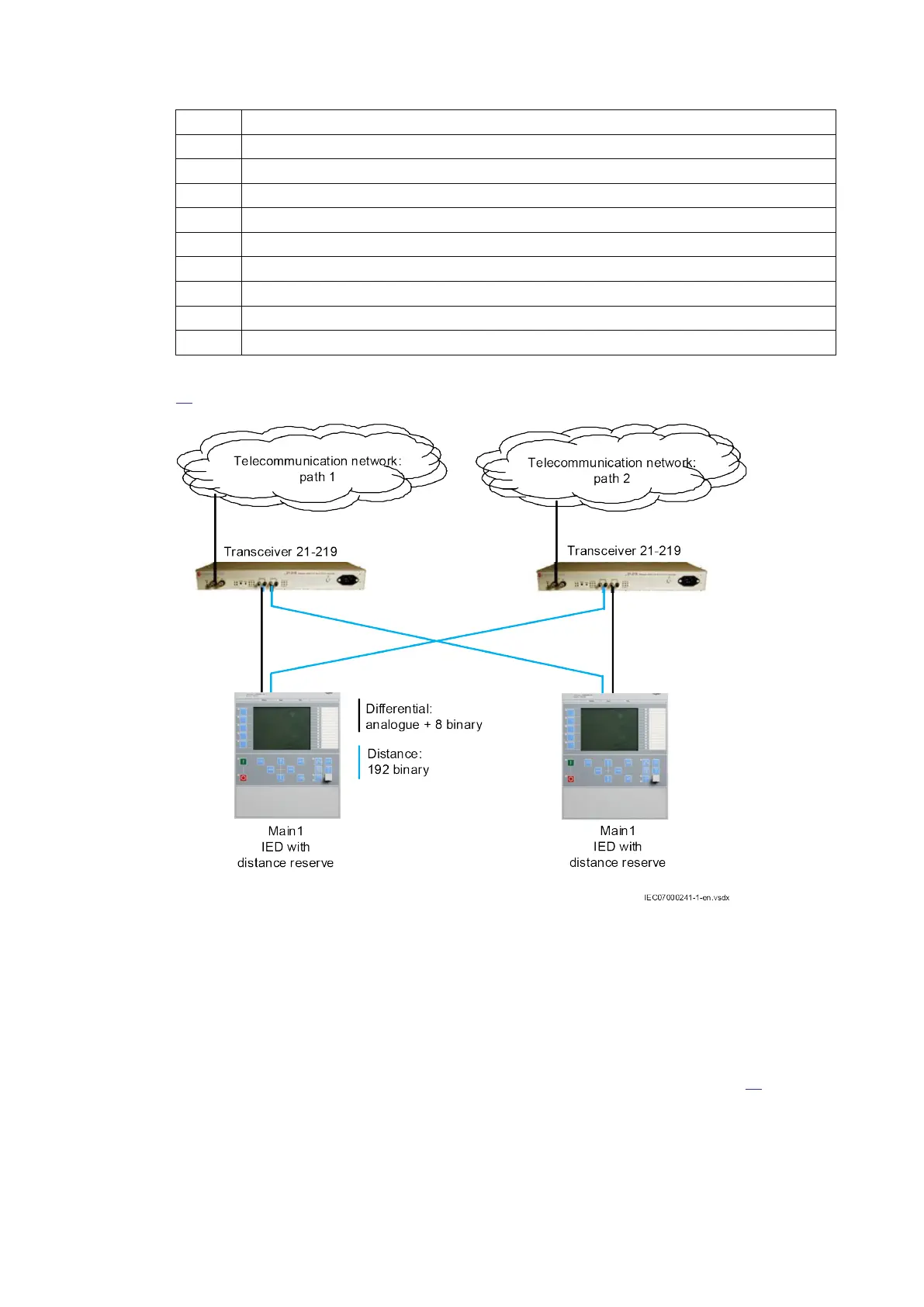
Transceiver 21-219 has two channels that can be used for redundant communication (see Figure
83).
IEC07000241 V2 EN-US
Figure 83: Protection system with redundant communication channels
Configuration in normal use
No configuration is needed in normal use. When two transceivers are connected back-to-back (E1
ports connected to each other), one of the transceiver should be set to act as master.
Clock configuration switch
A rotary switch is included in the front panel to ease installation and testing (see Figure
84)
Clock synchronization configuration
The rotary switch on the front panel has 16 positions (HEX switch). At position 0 the switch’s arrow,
visible through the adjusting hole, points straight down.
Section 5 1MRK505382-UEN Rev. K
Communication set-up
82 Communication set-up, 670/650 series
Application Guide
© 2017 - 2023 Hitachi Energy. All rights reserved
 Loading...


