Table 32: LED indicators used for detecting communication faults
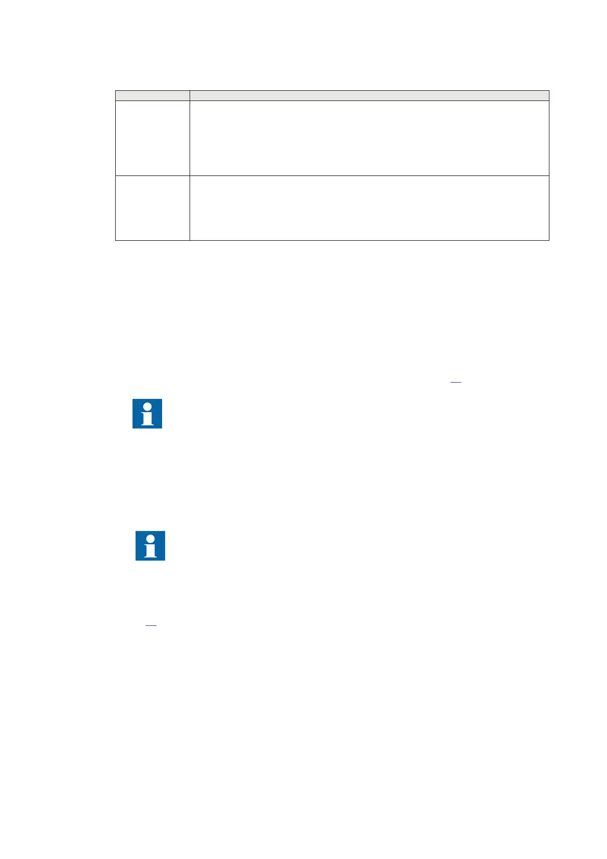
LED name Fault indication
LA Local Alarm. Red LED indicates that transceiver 21-219 has detected a fault condition in the
C37.94 protocol (LOS = Loss Of Signal). The Yellow Alarm bit is set in the outgoing C37.94
protocol.
The red LED is lit when transceiver 21-219 has detected an error. The indication has a memory
function. When the local error is no longer present, the LED blinks until the Reset button is
pressed.
RA Remote Alarm. Red LED indicates that the remote unit has detected a fault condition, and has
set the Yellow Alarm bit in the C37.94 protocol.
The red LED is lit when the fibre-optic link has detected an error. The indication has a memory
function. When the remote error is no longer present, the LED blinks until the Reset button is
pressed.
If the line differential protection IED shows a communication fail alarm but LA or RA LED is not lit on
transceiver 21-219, communication interruption stems from the telecommunication network.
5.7.4 Detecting communication faults through loop-back testing
GUID-990AA1AD-3BB4-4A80-AECF-A0E64A4AA996 v2
Loop-back tests are an efficient way to trace the origin of communication faults. Loop-back testing
means that loop-backs are created to the local line differential protection IEDs at different points in
the communication network. Testing encompasses both fibre-optic and galvanic cable loop-backs
depending on their actual positions in the communication network (see Figure
89).
Loop-back testing with X.21 galvanic interface requires special procedures and
equipment. Contact your local Hitachi Power grids representative for more details.
Procedure:
1. Block the trip circuits.
2. Set the local and remote terminals to have the same address (TerminalNo and RemoteTermNo)
on the local HMI under Main menu /Configuration /Communication /LDCM communication .
3. Select the synchronization method (GPS or echo).
In most cases, the synchronization method used in loop-back testing should be the same
as is used in actual service. However, in some test cases, for example with only a single
terminal, the external clock should be set as a master even though it is set as a slave in
actual service.
4. Perform the loop-back tests at consecutive points of the communication network. Number of
tests to be performed depends on the actual communication network and the number of
channels.
Figure
89 shows an example of a loop-back testing set-up.
Transceiver 21-216 is connected to a 64 kbit/s PDH multiplexer (PDH MUX). Transceiver 21-219 is
typically connected directly to a 2 Mbit/s SDH multiplexer (SDH MUX), which reduces the number of
interface points for loop-back testing.
Section 5 1MRK505382-UEN Rev. K
Communication set-up
90 Communication set-up, 670/650 series
Application Guide
© 2017 - 2023 Hitachi Energy. All rights reserved
 Loading...


