5.4.5 Communication via built-in X.21 galvanic interface
GUID-C0B90D43-0B15-4B17-835D-64114CF968E9 v1
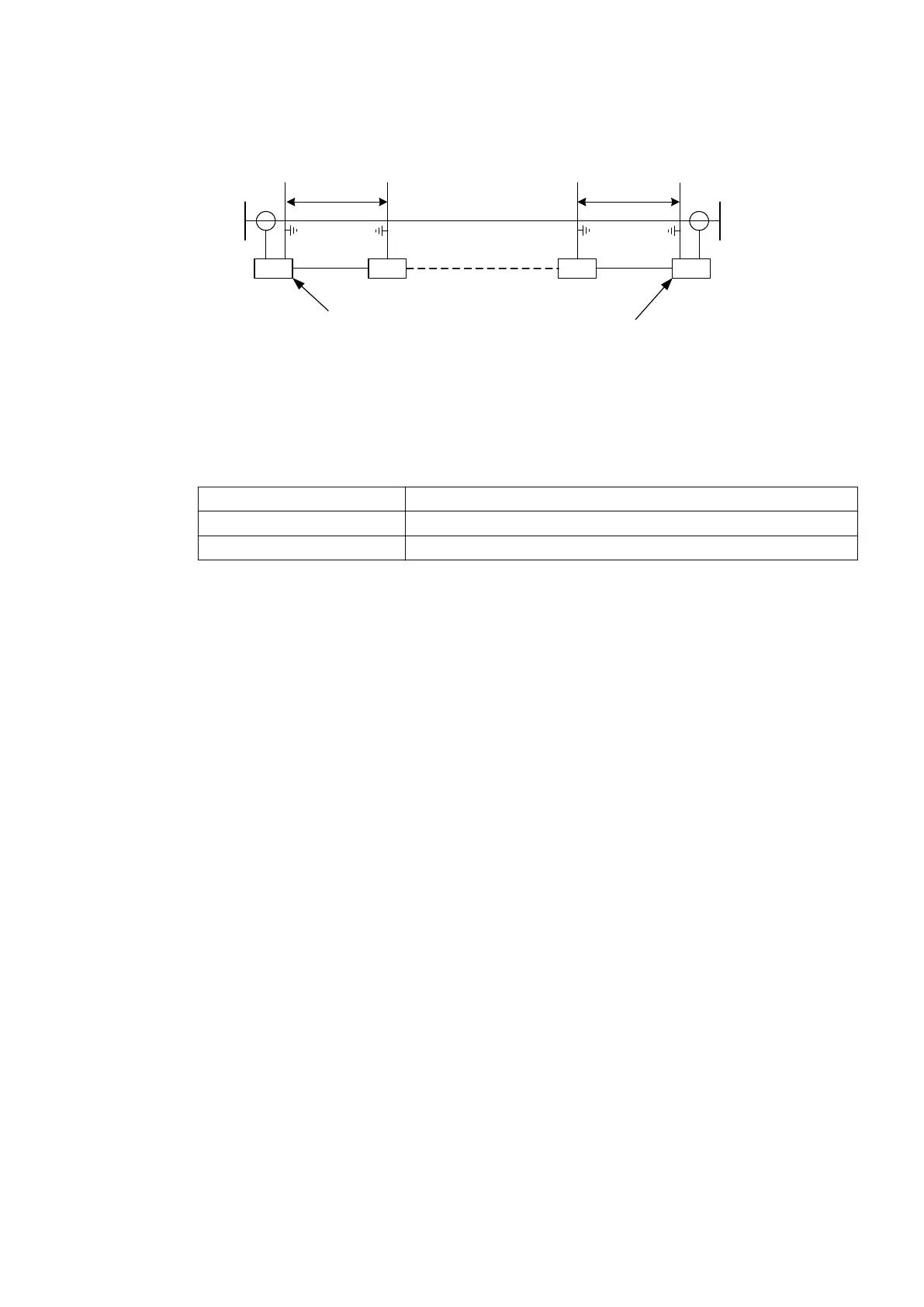
LOCAL REMOTE
< 10 m
IED
PCM
IED
Built-in X.21
galvanic
interface
Built-in X.21
galvanic
interface
IEC07000259-2-en.vsdx
< 10 m
PCM
IEC07000259 V2 EN-US
Figure 68: Communication structure via built-in X.21 galvanic interface
IED Terminal used for binary signal transfer
X.21 Built-in galvanic iterface
PCM Pulse code multiplexer
5.4.5.1 Service settings for the line differential protection IED with X.21 galvanic
interface
GUID-66F9DFE3-3D64-4CDB-97D8-19D13F56EA55 v2
X.21 Micro D-sub 15–pole male connector according to V11 (X:27) balanced version is used for X.21
communication.
5.4.5.2 PDH telecommunication via C37.94 interface to external transceiver
C37.94-X.21
GUID-65BB5DA1-51AC-45CA-A482-FE0EB48CB622 v2
When the distance between IED and PCM equipment is more than 10 meters and an X.21 interface
on the PCM needs to be used, it can be accomplished by using an external converter from C37.94 to
X.21.
1MRK505382-UEN Rev. K Section 5
Communication set-up
Communication set-up, 670/650 series 71
Application Guide
© 2017 - 2023 Hitachi Energy. All rights reserved
 Loading...


