GUID-4051693B-04FA-4C97-8D56-721BE91FC90C V1 EN-US
The ACT part for station B and station C must include the two 3-phase groups of received current.
The first group (CH 1-3) is for the current measured at station A received through the communication
link between stations (A-B and A-C). The second group (CH4-CH6) is for the current received
through the link forward feature. The number of CT used for the line differential protection function
must be set to 3 at all stations. Remote tripping is always included in the data used for link forward.
No configuration is required.
4.6 Configurations with power transformers in the
protected zone
4.6.1 Line differential protection L3CPDIF, L6CPDIF, LT3CPDIF,
LT6CPDIF
4.6.1.1 Power transformers in the protected zone
M12541-6 v7
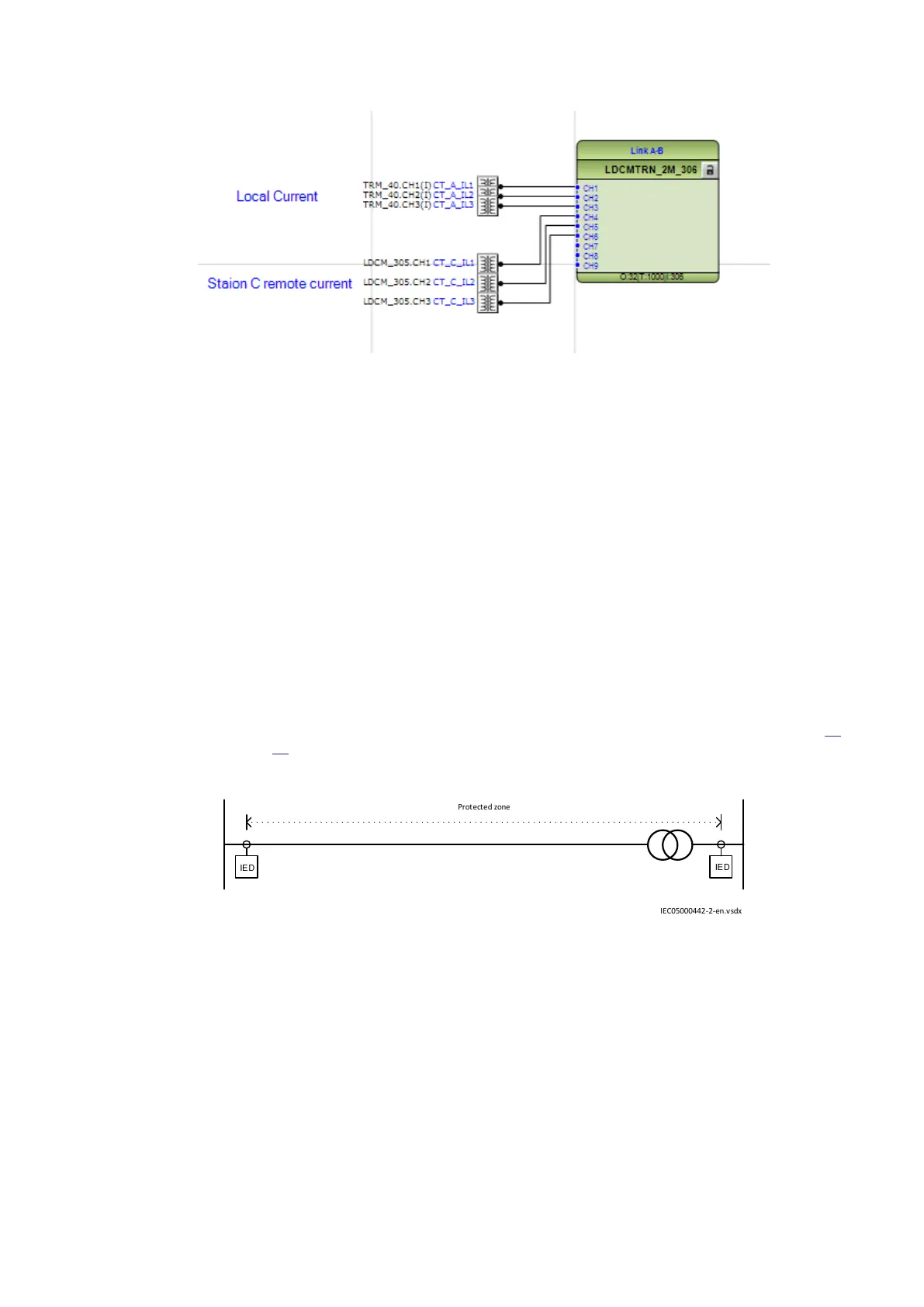
One three-winding transformer or two two-winding transformers can be included in the line protection
zone. The alternative with one two-winding transformer in the protected zone is shown in Figure
26
and Figure 27.
IED
IE D
Protected zone
IEC05000442-2-en.vsdx
IEC05000442 V2 EN-US
Figure 26: One two–winding transformer in the protected zone
1MRK505382-UEN Rev. K Section 4
Analog and binary signal transfer for line differential protection
Communication set-up, 670/650 series 29
Application Guide
© 2017 - 2023 Hitachi Energy. All rights reserved
 Loading...


