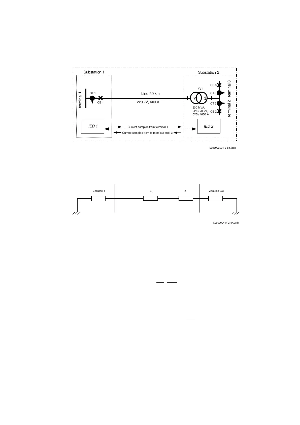
The circuit is protected by two terminals 1 and 2. These terminals process the same data except for
minor distortion in data that takes place during communication between them. Both terminals operate
as masters. If at least one of them indicates an internal fault, the protected circuit is disconnected.
IED 2
Line 50 km
CT 3
Substation 2
Substation 1
Current samples from terminals 2 and 3
Current samples from terminal 1
CT 2
Yd1
200 MVA,
220 / 70 kV,
525 / 1650 A
Y
d
220 kV, 600 A
CB 1
terminal
2 terminal
3
CB 2
CB 3
terminal
1
CT 1
IED 1
IEC05000534-2-en.vsdx
IEC05000534 V2 EN-US
Figure 35: Line differential protection with a power transformer in the protected zone
Z
L
Z
T
Zsource 2/3Zsource 1
IEC05000444-2-en.vsdx
IEC05000444 V2 EN-US
Figure 36: Circuit impedances
where:
Line data is
EQUATION1419 V1 EN-US
Transformer data is
2
220
10 220
% 10% 24.2
100 200
T
X X= Þ = × = W
EQUATION1420 V1 EN-US
Source impedance is
EQUATION1421 V1 EN-US
2
Source2 / 3 Source2 / 3 220
220
Z 5 (Z ) 5 49.4
70
= W Þ = × = W
æ ö
ç ÷
è ø
EQUATION1422 V1 EN-US
1MRK505382-UEN Rev. K Section 4
Analog and binary signal transfer for line differential protection
Communication set-up, 670/650 series 33
Application Guide
© 2017 - 2023 Hitachi Energy. All rights reserved
 Loading...


