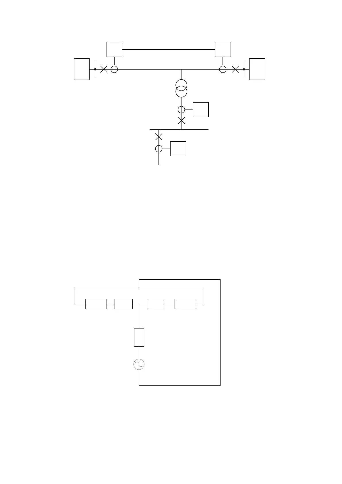
IEC12000193-2-en.vsd
3Id> 3Id>
SA
1700
MVA
SA
1280
MVA
10MVA
ek=10%
138/10kV
3Id>
3Id>
A B
IEC12000193 V2 EN-US
Figure 37: Setting example
Input data to calculation:
• Apparent source power at A side: Ss
A
= 1700 MVA
• Line impedance from A to tap: Zl
A
= 2.8 Ω
• Line impedance from tap to B side: Zl
B
= 1.2 Ω
• Apparent source power at B side: Ss
B
= 1280 MVA
• Base current of differential current protection: I
Base
= 42 A
• Apparent power of transformer: S
n
= 10 MVA
• Short circuit impedance of transformer: e
k
= 10%
• Nominal voltage on transformer high voltage winding: U
n
= 138 kV
Fault current on the high voltage (HV) side of the tap transformer is calculated for a three-phase fault
on the low voltage (LV) side. 138 kV is chosen as calculation voltage.
ZsA ZsB
Z
t
r
f
E
ZlA Zl B
IEC14000046-1-en.vsd
IEC14000046 V1 EN-US
Figure 38: Thevenin equivalent of the tap transformer
Converting the sources into impedances gives:
1MRK505382-UEN Rev. K Section 4
Analog and binary signal transfer for line differential protection
Communication set-up, 670/650 series 37
Application Guide
© 2017 - 2023 Hitachi Energy. All rights reserved
 Loading...


