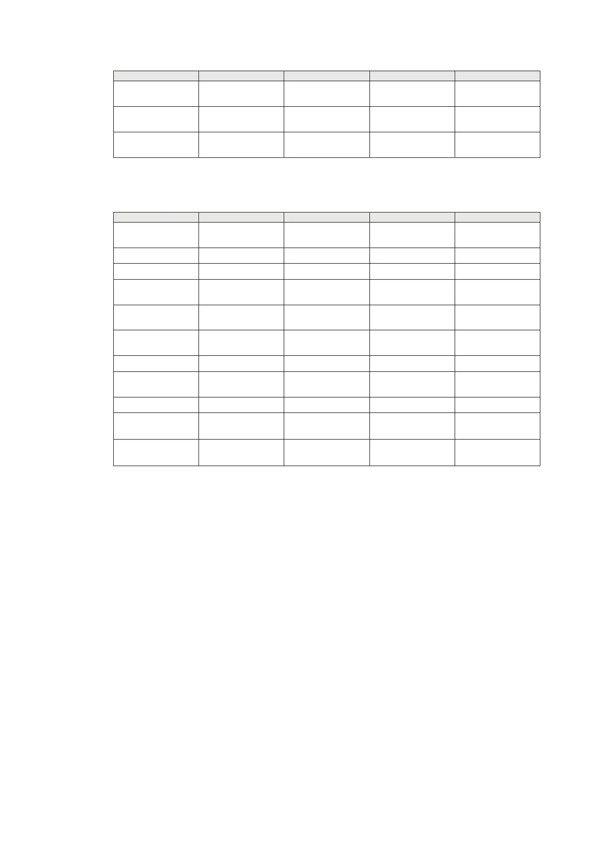
Type of LDCM Short range (SR) Short range (SR) Medium range (MR) Long range (LR)
Factory splice
attenuation
0.5 dB/splice
0.3 splices/km
0.5 dB/splice
0.1 splices/km
0.08 dB/splice
0.1 splices/km
0.08 dB/splice
0.1 splices/km
Repair splices 0.25 dB/splice
0.1 splices/km
0.25 dB/splice
0.1 splices/km
0.1 dB/splice
0.05 splices/km
0.1 dB/splice
0.05 splices/km
Fiber margin for
aging
0.1 dB/km 0.1 dB/km 0.01 dB/km 0.01 dB/km
Table 13: Example of calculating the optical budget (maximum distance)
Type of LDCM Short range (SR) Short range (SR) Medium range (MR) Long range (LR)
Type of fibre Multi-mode fiber
glass 50/125 μm
Multi-mode fiber
glass 62.5/125 μm
Single-mode fiber
glass 9/125 μm
Single-mode fiber
glass 9/125 μm
Modem type 1MRK0002122-AB 1MRK0002122-AB 1MRK002311-AA 1MRK002311-BA
Maximum distance 2 km 3 km 80 km 120 km
Attenuation in fibre-
optic cables
6 dB 9 dB 25.6 dB 25.2 dB
2 contacts 3
dB
3 dB 0.6 dB 0.6 dB
Factory splice
attenuation
0.5 dB 0.5 dB 0.64 dB 0.96 dB
Repair splices 0.25 dB 0.25 dB 0.4 dB 0.6 dB
Fiber margin for
aging
0.2 dB 0.3 dB 0.8 dB 1.2 dB
Total attenuation 9.95 dB 13.05 dB 28.04 dB 28.56 dB
Optical link budget 11.8 dB 18.8 dB 28.8 dB
30.8 dB
1)
28.7 dB
Link margin 1.85 dB 5.75 dB 0.76 dB
2.76 dB
1)
0.14 dB
1) Applicable for revision r11 and later.
ComAlarmDel defines the time delay for communication failure alarm. In communication systems,
route switching can sometimes cause interruptions with a duration of up to 50 ms. Too short a time
delay can thus cause nuisance alarms.
ComAlrmResDel defines the time delay for communication failure alarm reset.
RedChSwTime defines the time delay before switching over to a redundant channel in case of
primary channel failure.
RedChRturnTime defines the time delay before switching back to the primary channel after channel
failure.
AsymDelay denotes asymmetry which is defined as transmission delay minus receive delay. If fixed
asymmetry is known, Echo synchronization method can be used, provided that AsymDelay is
properly set. From the definition follows that asymmetry is always positive at one end and negative at
the other end.
MaxTransmDelay indicates maximum transmission delay. Data for maximum 40 ms transmission
delay can be buffered up. Delay times in the range of some ms are common. If data arrive in wrong
order, the oldest data is disregarded.
Section 4 1MRK505382-UEN Rev. K
Analog and binary signal transfer for line differential protection
56 Communication set-up, 670/650 series
Application Guide
© 2017 - 2023 Hitachi Energy. All rights reserved
 Loading...


