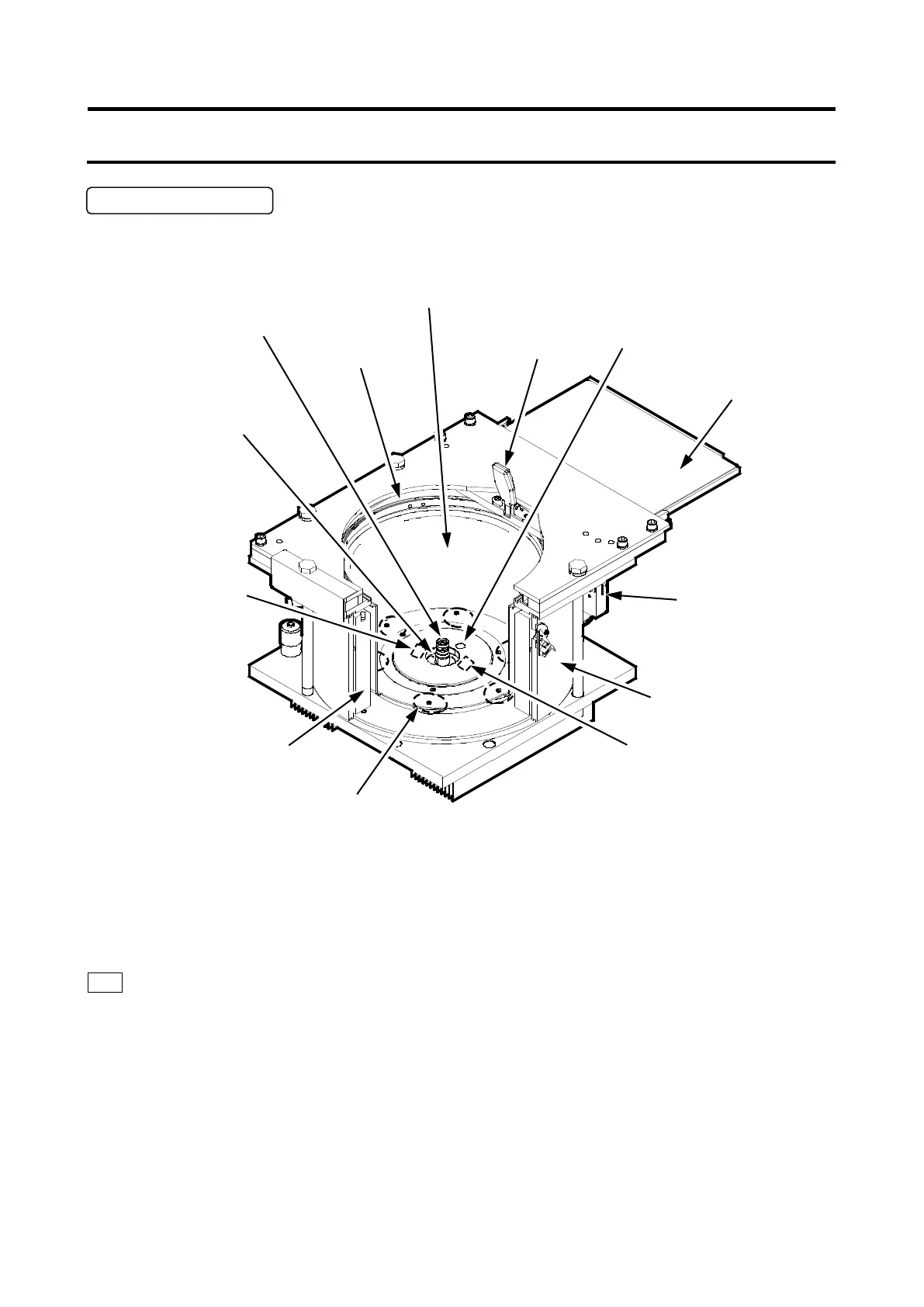
The structure of the rotor chamber (vacuum chamber) is shown in Fig. 2-2-2.
Fig. 2-2-2 Rotor chamber
Note:
If sample or water drops to the window of the temperature sensor or the RLM sensor, it may cause an
incorrect detection. Whenever the sensor is wet, wipe it with a clean, dry cloth. Take care not to
scratch the surface of the sensor.
Drive shaft (crown)
Chamber door seal
Handle
Chamber
door
Temperature sensor (measuring
the temperature of the rotor)
Bowl (Rotor Chamber)
Magnetic head for rotor life management (RLM)
sensor (reading and writing information on the life
of the rotor with RLM adapter)
Thermoelectric cooling element
Overspeed detector
(detecting any instance
exceeding the maximum
allowable speed of the rotor)
Speed sensor
:
2-6
 Loading...