7 Servicing
RCD-(0.8-6.0)FSR - 2-way cassette
SMGB0137 rev.0 - 05/2021
204
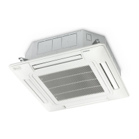
7.3.3 Removal of the optional air panel
1 Open the air inlet grille.
2 Remove the electrical box cover.
3 Remove the connector (CN17) of the automatic louver on the indoor unit
PCB.
4 Hang the air panel from the indoor unit by hooking the hinges and
remove the long screws (4 for P-AP90DNA, 6 for P-AP160DNA) for air
panel.
5 Then, remove the air panel by unhooking the hinges (x2) from the indoor
unit drain pan.
CN17
PCB
CN14
THM2
CN36 CN1
11
Electrical box
Hinge (x2)
Long screw (x2)
(Inside the Air Outlet)
(Only for P-AP160DNA)
Long screw (x4)
7.3.4 Removal of the fan duct and the fan
1 Remove the electrical box cover according to the item “7.1.2 Removing
electrical box cover”.
2 Remove the electrical box.
a. Remove the outlet air thermistor (THM2), the drain-up mechanism
connector (CN36), the oat switch connector (CN14), the liquid
pipe and gas pipe thermistors (THM5, THM3), the expansion valve
(CN11), the fan motor connector (CN1) and the auto louver motor
connector (CN17) from the PCB.
For RCD-(4.0-6.0)FSR, remove the fan control lead wire (x2) from
the bell-mouth then remove the fan motor connector (CN4) inside the
fan control electrical box.
b. Remove the 2 xing screws for the electrical box and remove the
electrical box.
For RCD-(4.0-6.0)FSR, remove the 2 xing screws for the fan control
electrical box and remove the fan control electrical box.
CN17
CN14
CN36 CN1
11
Electrical box
3 Removing the Bell-mouth. Remove 4 xing screws for the bell-mouth xed to the drain pan, and remove the bell-
mouth (1 Bell-mouth for RCD-(0.8-3.0)FSR, 2 bell-mouth for RCD-(4.0-6.0)FSR).

 Loading...


