3 Electrical and control settings
Unit electrical wiring and connection
SMGB0137 rev.0 - 05/2021
38
3.1 Unit electrical wiring and connection
3.1.1 Transmission wiring between outdoor and indoor unit
• The transmission is wired to terminals 1-2.
• The H-LINK II wiring system requires only two transmission cables that connect the indoor unit and the outdoor unit.
1
1
2
2
Indoor unit
Outdoor unit
• Use twist pair wires (0.75 mm²) for operation wiring between outdoor unit and indoor unit. The wiring must consist of
2-core wires (Do not use wire with more than 3 cores).
• Use shielded wires for intermediate wiring to protect the units from noise interference, with a length of less than 300m
and a size in compliance with local codes.
• Intheeventthataconduittubeforeld-wiringisnotused,xrubberbushestothepanelwithadhesive.
! CAUTION
Ensure that the transmission wiring is not wrongly connected to any live part that could be damaged the PCB.
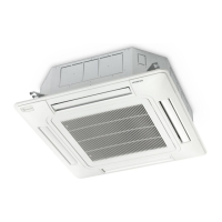
3.1.2 Electrical connection of RCI units
Work prior to the electrical connection
1 Turnothepowersupplyswitchesbeforestartingworkandttheappropriatelocksandsafetywarnings.
2 Wait5minutesafterturningothepowersupplyswitches.
3 Checkthatthefansontheindoorandoutdoorunitsareatastandstillbeforestartingwork.
? NOTE
• Theelectricalpowerfortheunitmustinvolveaspecicpowerline,withanexclusivepowercontrolswitchandresidualcurrentbreaker,
installed in line with local or national safety regulations.
• Checkthattheelectricalpowerlinehasenoughcapacitytosupplytheunit.Itslength,thecablediameterandtheirprotection(sleeve
orjacket)mustbeappropriatefortheunit.
• Forfurtherinformation,alwaysconsiderthecurrentregulationsinthecountrywheretheunitistobeinstalled.
! CAUTION
• Riskofre:cablesmustnevertouchtherefrigerantpipes,printedcircuitboards(PCB),sharpedgesorelectricalcomponentsinside
the unit to avoid damaging them.
• Looseconnectionterminalsmayleadtocableandterminaloverheating.Theunitmayoperateincorrectly,leadingtoariskofre.
Checkthatthecablesarermlysecuredtotheconnectionterminals.
Electrical connection
CheckthatthepowersupplyfortheRCIindoorunitis230V.Ifnot,replacetheCNconnectorsontheTFtransformersin
theelectricalbox.
Maketheconnectionbetweentheindoorunitandtheairpanel.
? NOTE
• Topreventthescrewsfromfallingfromtheterminalstrip,donotremovethemcompletely,holdontotheterminalandcheckthatthe
screw is secure through the hole.
• Usethefollowingscrewsfortheterminalstrip:
- M4 screw for the power supply.
- M3.5 screw for the communication line.

 Loading...


