3 Electrical and control settings
Unit electrical wiring and connection
SMGB0137 rev.0 - 05/2021
42
Followthestepsbelowtoconnecttheearthwiretotheearthconnectionintheelectricalbox:
1 Wherenecessary,loosenthescrewontheearthingconnectionintheelectricalbox.
2 Connect the shielded part of the power supply earth wire and the signal wiring earth wire to the earth connection.
3 Tightenthescrewontheearthingconnectionintheelectricalbox.
4 Checkthattheshieldedpartoftheearthingcablesarecorrectlysecured.
Firmlysecurethecablesusingatieinsidetheelectricalbox.
Cover the cables and the hole using a sealant to protect them from condensation and insects.
Test runs
! CAUTION
• Becarefulduringthetestruns,assomeofthesafetyfunctionsremaindisabled:theunitsoperatefortwohourswithoutswitchingo
via the thermostat. The three-minute compressor protection is not enabled during the test.
• Secure the rubber bushes to the panel using adhesive when the outdoor unit ducts are not used.
• The compressor remains at a standstill during forced stoppage.
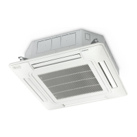
3.1.4 Electrical connection of RCD units
Work prior to the electrical connection
1 Turnothepowersupplyswitchesbeforestartingworkandttheappropriatelocksandsafetywarnings.
2 Wait5minutesafterturningothepowersupplyswitches.
3 Checkthatthefansontheindoorandoutdoorunitsareatastandstillbeforestartingwork.
? NOTE
• Theelectricalpowerfortheunitmustinvolveaspecicpowerline,withanexclusivepowercontrolswitchandresidualcurrentbreaker,
installed in line with local or national safety regulations.
• Checkthattheelectricalpowerlinehasenoughcapacitytosupplytheunit.Itslength,thecablediameterandtheirprotection(sleeve
orjacket)mustbeappropriatefortheunit.
• Forfurtherinformation,alwaysconsiderthecurrentregulationsinthecountrywheretheunitistobeinstalled.
! CAUTION
• Riskofre:cablesmustnevertouchtherefrigerantpipes,printedcircuitboards(PCB),sharpedgesorelectricalcomponentsinside
the unit to avoid damaging them.
• Looseconnectionterminalsmayleadtocableandterminaloverheating.Theunitmayoperateincorrectly,leadingtoariskofre.
Checkthatthecablesarermlysecuredtotheconnectionterminals.
Electrical connection
CheckthatthepowersupplyfortheRCDindoorunitis220-240V.Ifnot,replaceconnectorsCN27andCN28ontheTF
transformersintheelectricalbox.
Followthestepsbelowtoconnecttheremotecontrolcableortheoptionalextensionwire:
1 Passthecablethroughtheknock-outholeinthecabinet.
2 Connect the cable to terminals A and B of the terminal strip (TB2).
3 Tighten the screw on terminals A and B.
4 Checkthatthecablesarecorrectlysecured.
Connector for 240V
Connector for 220V
Followthestepsbelowtoconnectthepowercablestotheterminalstrip(TB1):
1 Where necessary, loosen the screws on terminals L1 and N on the terminal strip (TB1)
2 Connect the power cables to terminals L1 and N.
3 Tighten the screws on terminals L1 and N.
4 Checkthatthecablesarecorrectlysecured.

 Loading...


