3 Electrical and control settings
Wiring diagrams
SMGB0137 rev.0 - 05/2021
74
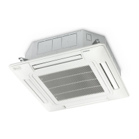
3.3.12 RPF(I)-(1.0-2.5)FSN2E
Air
inlet
Air
outlet
Liquid
Gas
Main
switch,
CB
(Fuse),
ELB
ElectricalcontrolboxforIndoorunit
Operation line
DC 5V
Wired remote control switch
Mark Name
CA Capacitor
CNn Connector on PCB
PCNn Power connector on PCB
DSW3-7 DIP switch for setting
RSW1,2 Rotary switch for setting
EFR1 Power supply fuse
EF2 PCB fuse
EF3 Fuse for PCN5 connector
MIF Motor for Indoor fan
MV Micro-computercontrolexpansionvalve
PCB Printed circuit board
Mark Name
TB1,2 Terminal board
THM1-5 Thermistor
TF Transformer
ITI Internal thermostat for indoor fan motor
CN22-27 Aerial connector
YH1 Relay for HI fan motor tap
YME Relay for ME fan motor tap
YLO Relay for LO fan motor tap
YSLO Relay for SLO fan motor tap
1~ 230V 50Hz

 Loading...


