3 Piping work and refrigerant charge
Refrigerant and drain hose installation
SMGB0099 rev.0 - 12/2016
109
3
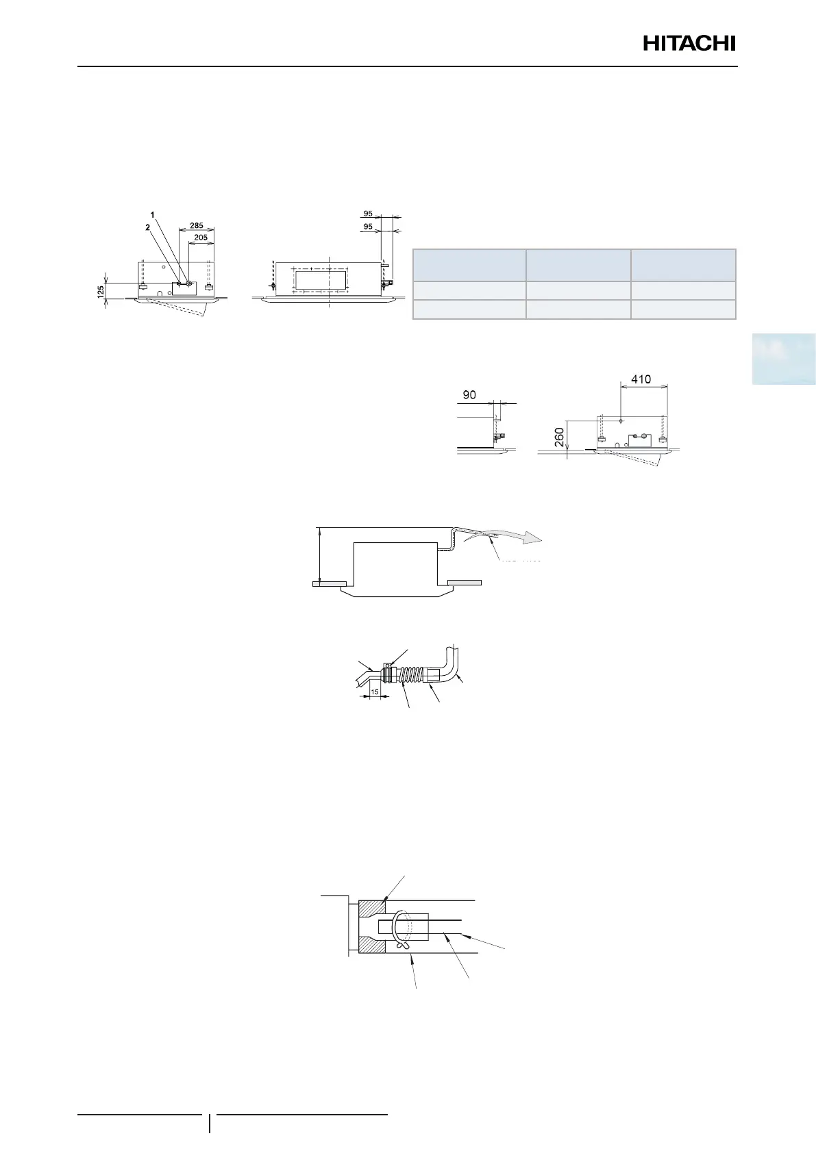
3.5.3 RCD-(0.8-6.0)FSN3 - 2-way cassette
Refrigerant pipe installation
The correct position for the refrigerant pipe connection is shown below. The pipe connection must be accessible from all
directions (above, left or right).
Models
(1) Gas pipe mm
(inches)
(2) Liquid pipe
mm (inches)
RCD-(0.8/2.0)FSN3 Ø12.70 (1/2) Ø6.35 (1/4)
RCD-(2.5–6.0)FSN3 Ø15.88 (5/8) Ø9.52 (3/8)
Drain pipe installation
The correct position for the drain hose connection is
shown below.
Prepare a polyvinyl chloride (PVC) pipe with an outer
diameter of 32 mm.
Secure the pipe with the clamp and adhesive supplied.
The drain hose must have a gradient of 1% (1/100) to 4% (1/25).
Max. 500mm
1/25~1/100
Down
Gradient of drain piping
1/25~1/100
down slope
Drainage pipe
connection
Clamp (accessory)
Do not use adhesive
PVC pipe ∅ 32
(eld-supplied)
Use PVC
adhesive
Drainage pipe
(accessory)
! CAUTION
• Do not apply adhesive between the drain hose connection and the drain hose.
• Do not apply too much force when making the drain hose connection as this could damage it.
• Do not use bent or twisted drain pipes as these will cause water leaks.
Then insulate the drain hose appropriately.
1/25~1/100
Down slope
Insulation (Field-Supplied)
Insulation (Factory-Supplied)
Clamp (Factory-Supplied)
Polyvynil Chloride Tube
(Field-Supplied)
Insulation
(factory supplied)
Clamp (factory supplied)
Insulation (eld supplied)
Polyvynil chloride
tube (eld supplied)
1/25~1/100
down slope
? NOTE
If there is excessive clearance between the drain pipe connection and the drain hose, add a sealing material between both parts in order
to t and not deform the drain hose.
 Loading...

