4 Electrical and control settings
Wiring diagrams for indoor units and complementary systems
SMGB0099 rev.0 - 12/2016
182
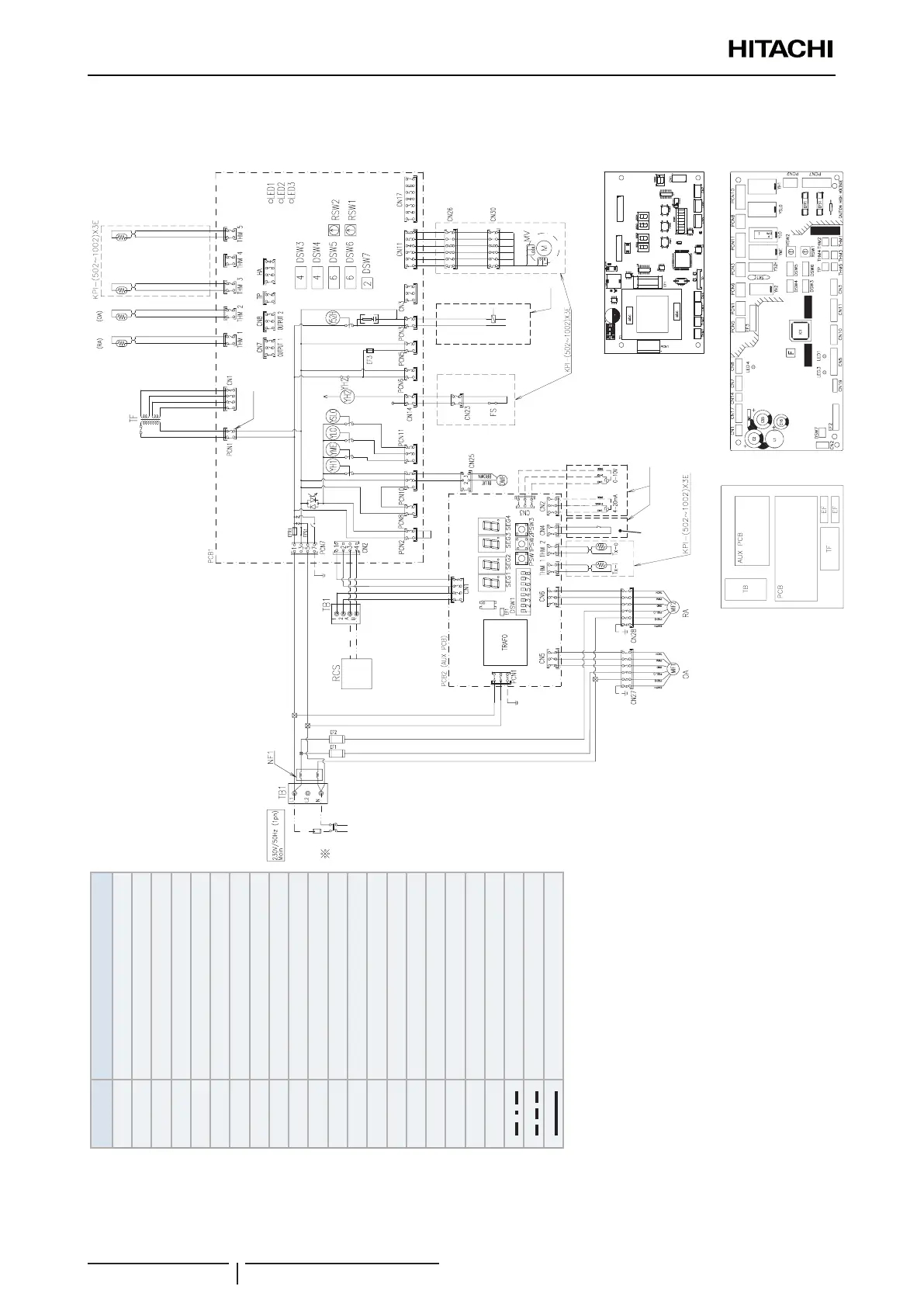
4.3.2 Wiring diagrams for complementary systems
KPI-(252-2002)E4E energy recovery unit and KPI-(502-1002)X4E active unit
Mark Name
DSW Dip switch for settings
RSW
1,2
Rotary switch for settings
EF
1, 2
Fuse
EFR
1
Fuse
PCNn Power connector
CNn Connector
SEGx Display
MIF Motor for Indoor fan
LED
1~3
Alarm code
PCB Printed circuit board
RCS Remote control switch
TB Terminal Board
TF Transformer
THM Thermistor
DMP Damper
PSWx Push button
NF1 Noise lter
MV Expansion valve
OA Outdoor air
RA Return air
Field wiring
Earth wiring
Factory wiring
Main
switch
(Main PCB)
Air
Outlet
Air
inlet
Liquid Gas<Blue> <Red>
For 230V
fan fan
Option
Inlet Outlet
DX Coil
CO2 sensor
ON/OFF
CO2 Sensor
PCB1 Sockets location
PCB2 Sockets location
Electrical box
 Loading...

