5 Control system
Printed circuit board for RPI(M)-(0.6-6.0)FSN4E
SMGB0099 rev.0 - 12/2016
191
5
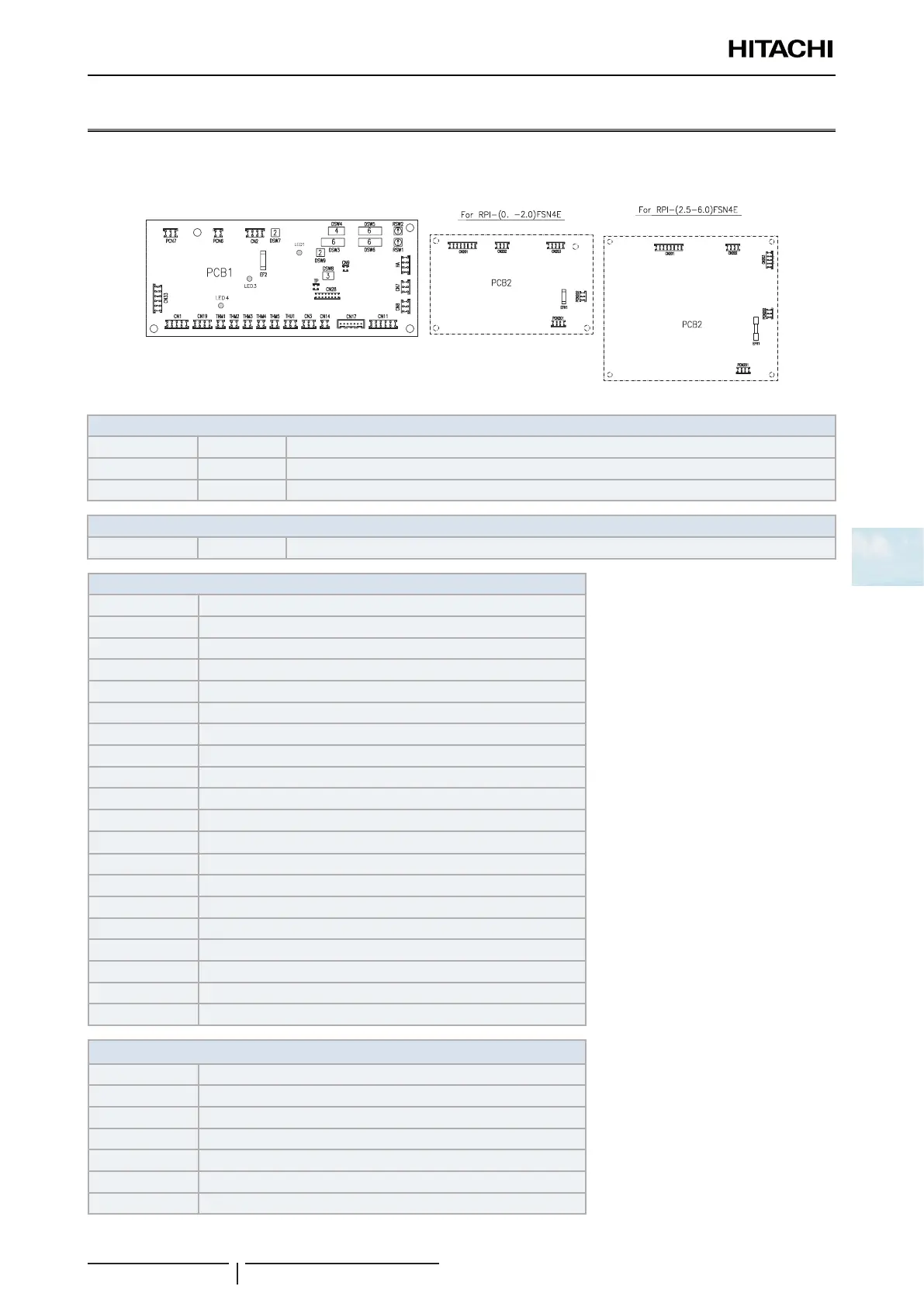
5.6 Printed circuit board for RPI(M)-(0.6-6.0)FSN4E
The indoor unit PCB operates with four types of DIP switches, a slide switch and a rotary switch. The position is as
follows:
8
PCB1 LED indicator
LED1 Red This LED indicates the transmission status between the indoor unit and the remote control.
LED3 Yellow This LED indicates the transmission status between the indoor unit and the outdoor unit.
LED4 Red PCB power supply
PCB2 LED indicator
LED1 Yellow PCB power supply
Connector indication
PCN6 Drain pump
PCN7 Printed circuit board 2
PCN201 Terminal board
PCN202 Printed circuit board 1
THM1 Air inlet thermistor
THM2 Air outlet thermistor
THM3 Liquid pipe thermistor
THM5 Gas pipe thermistor
CN1 Printed circuit board 2
CN2 Terminal board
CN3 Not used
CN11 Expansion valve
CN14 Float switch
CN17 Econofresh kit connection
CN19 Printed circuit board 2
CN201 Motor for indoor fan
CN202 Printed circuit board 1
CN203 Printed circuit board 1
EFR1 PCB2 fuse
EF2 PCB1 fuse
Switch indication
DSW3 Capacity code
DSW4 Unit model code
DSW5, RSW2 Refrigerant cycle number
DWS6, RSW1 Indoor unit number settings
DSW7 Fuse re-establishing
DSW8 Additional functions
DSW9 0.6HP capacity setting
 Loading...

