9 Servicing
RPIM-(0.6-1.5)FSN4E - Ducted indoor unit
SMGB0099 rev.0 - 12/2016
304
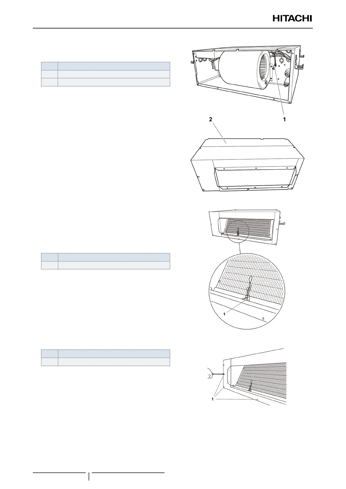
1 Remove the screws securing the rear cover of the unit.
2 Disconnect and remove the thermistor.
Nº Part
1 Location of the air inlet thermistor
2 Rear cover
9.8.3 Outlet air thermistor
? NOTE
• The thermistor is located on the outlet side of the unit.
• To disconnect and remove the appropriate thermistor, previously
see the chapter corresponding to the wiring diagrams in this Manual.
1 Disconnect and remove the thermistor.
Nº Part
1 Outlet thermistor
? NOTE
• The thermistor is located on the outlet side of the unit.
• To disconnect and remove the appropriate thermistor, previously
see the chapter corresponding to the wiring diagrams in this
Manual.
2 Disconnect and remove the thermistor. Removal of the
thermistors from the liquid and gas pipes.
Nº Part
1 Screws
? NOTE
• To disconnect and remove the appropriate thermistor, previously
see the chapter corresponding to the wiring diagrams in this
Manual.
• Cover the thermistors with cork tape or pipe insulation, depending
on the location. Both materials are factory-supplied. Replace
them if damaged during maintenance work.
 Loading...

