5 Control system
Printed circuit boards for RCIM-FSN4(E) indoor units
SMGB0099 rev.0 - 12/2016
187
5
5.2 Printed circuit boards for RCIM-FSN4(E) indoor units
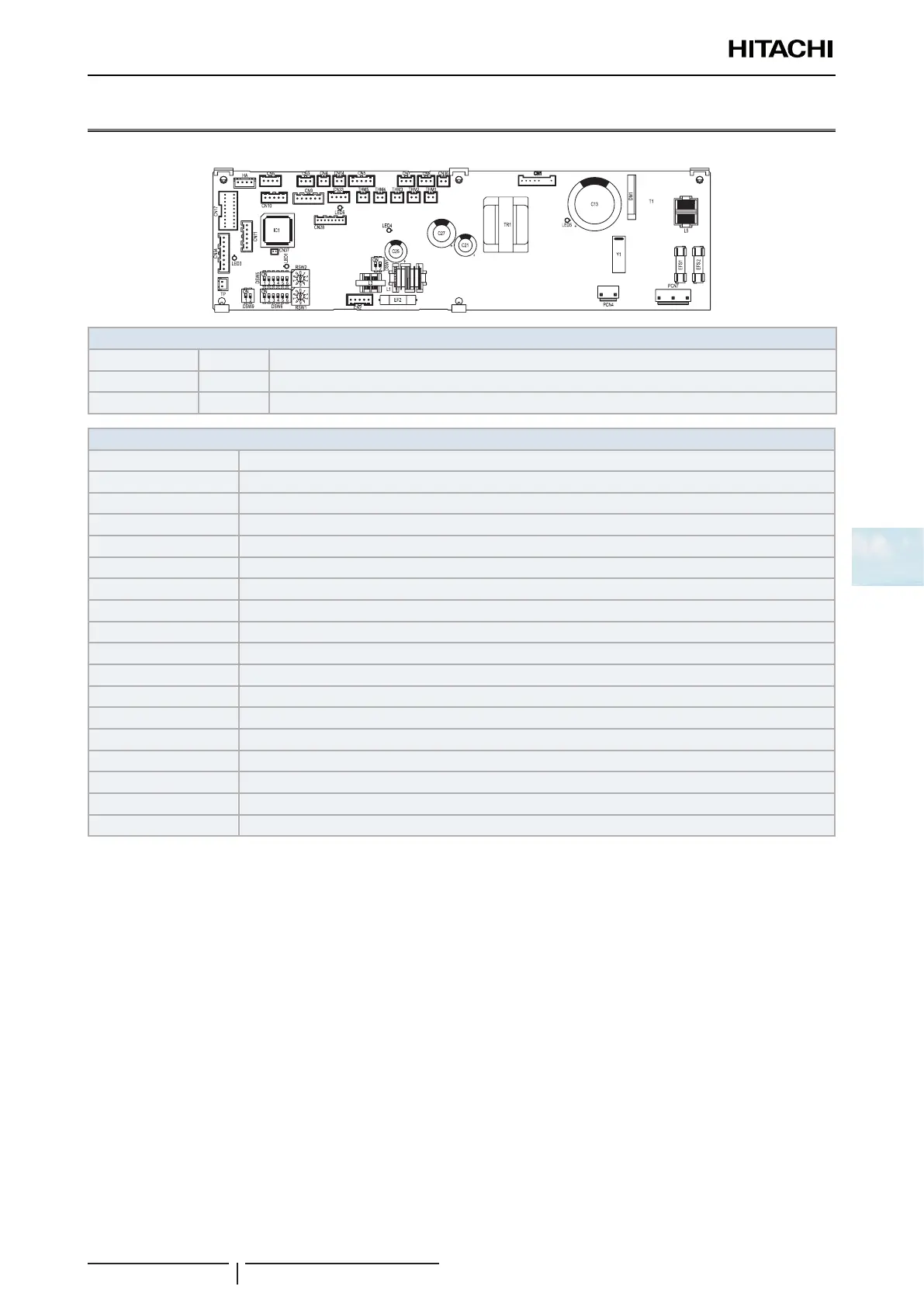
The indoor unit PCB operates with ve types of DIP switches and two rotary switches. The position is as follows:
LED indicator
LED 1 Red This LED indicates the transmission status between the indoor unit and the remote control
LED 2 Yellow This LED indic*ates the transmission status between the indoor unit and the outdoor unit
LED 3 Red PCB power supply
Connector indication
CN3 Optional connector (For signal input)
CN7, 8 Optional connector (For signal output)
CN10 Optional connector (For motion sensor)
DSW3, 4, 7, 9 Dip switch for setting
EFR1,2 Fuses
EF2 Fuse
MIF Motor for indoor fan
MS Motor for automatic swing louver
MV Micro-computer control expansion valve
PCB1 Printed circuit board
RSW1 Rotary switch for unit number setting (Ones digit)
DSW6 Dip switch for unit number setting (Tens digit)
RSW2 Rotary switch for refrigerant cycle number setting (Ones dit)
DSW5 Dip switch for refrigerant cycle number setting (Tens digit)
TB1, 2 Terminal block
THM1~3, 5 Thermistor
THM4 Optional connector (For remote temperature sensor)
CN4~6, HA, PCN4 Reserved connector on PCB
 Loading...

