4 Electrical and control settings
Wiring diagrams for indoor units and complementary systems
SMGB0099 rev.0 - 12/2016
181
4
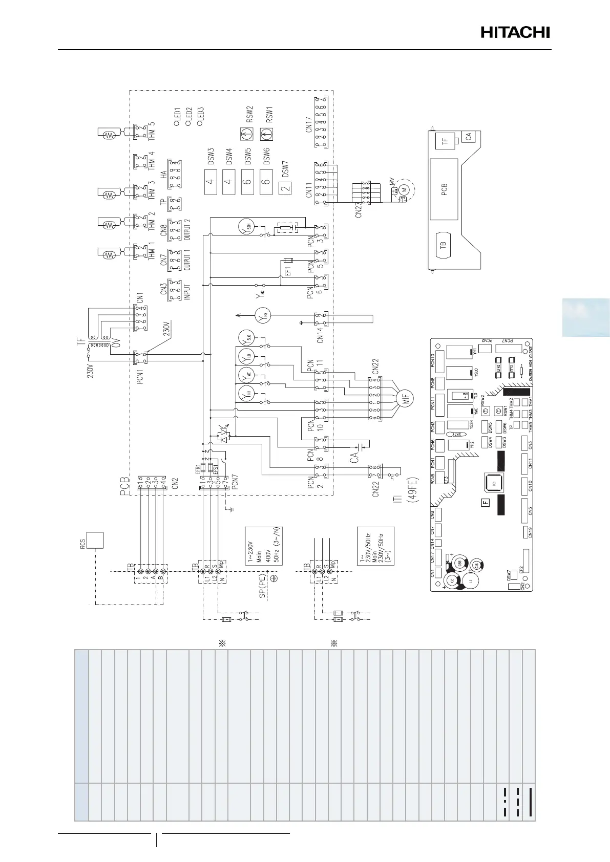
Wiring diagrams for the RPF(I)-(1.0-2.5)FSN2E indoor units
Air
inlet
Air
outlet
Liquid
Gas
Main
switch
Main
switch
Electrical control box for Indoor unitPrinted circuit board
For comunication
2 Wire RCS
Mark Name
CA Capacitor for Indoor fan
CN
21~26
Connector
DSW
3
Unit capacity code
DSW
4
Model
DSW
5
Refrigerant cycle nº
DSW
6
Unit code
DSW
7
Fuse recover/Remote control
selector
EFR
1
Fuse
EFS
1
Fuse
EHW(H2) Electric heater
ITI
Internal thermostat for Indoor unit
fan
MIF Motor for Indoor fan
MV Expansion valve
LED
1~3
Alarm code
PCB Printed circuit board
RCS Remote control switch
RSW
1
Indoor unit nº settings
RSW
2
Refrigerant cycle nº
SSW Slide switch
TB Terminal Block
TF Transformer
THM
1
Inlet air thermistor
THM
2
Outlet air thermistor
THM
3
Liquid pipe thermistor
THM
5
Gas pipe thermistor
YH
1
Relay for HI fan motor tap
Y
ME
Relay for ME fan motor tap
Y
LO
Relay for LO fan motor tap
Y
SLO
Relay for SLO fan motor tap
Field supplied
Field wiring
Earth wiring
Factory wiring
 Loading...

