4 Electrical and control settings
Wiring diagrams for indoor units and complementary systems
SMGB0099 rev.0 - 12/2016
183
4
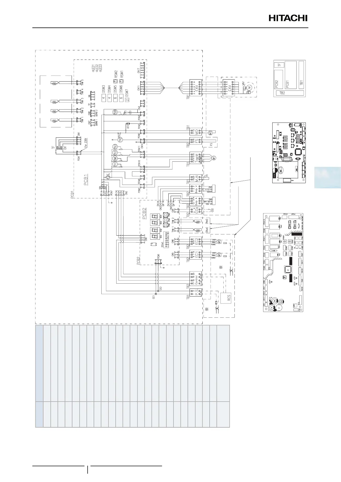
DX-Interface EXV-(2.0-10.0)E2
Main
switch
Main
switch
Connected directly to PCB
Optional
Field
installation
Expansion
valve
Option
Coil
inlet
Coil
outlet
Liquid Gas
(blue) (red) (black) (yellow)
Connected directly to PCB
Electrical control box
for DX-Kit 2
PCB2 Sockets location
PCB1 Sockets location
Mark Name
CNn Connector
PCNn Power connector
DSW
1~n
Dip switch for settings
EFR
1
Fuse
LED
1~3
Alarm code
PCB
1,2
Printed circuit board
RCS Remote control switch
RSW
1,2
Rotary switch for settings
TB Terminal Board
TF Transformer
THM Thermistor
Y
H2
Relay for drain motor
Y
H1
Relay for HI fan motor tap
Y
ME
Relay for ME fan motor tap
Y
LO
Relay for LO fan motor tap
Y
SLO
Relay for SLO fan motor tap
Y52H Relay for Electric heater
SEGx Display
PSW
1~3
Push button
MD Drain pump
DMP Damper
MF1 Top fan motor
MF2 EC Fan motor
MV Expansion valve
ITI
Internal thermostat for Indoor fan
motor
 Loading...

