Chapter 9 Inverter Functions
9-2-9
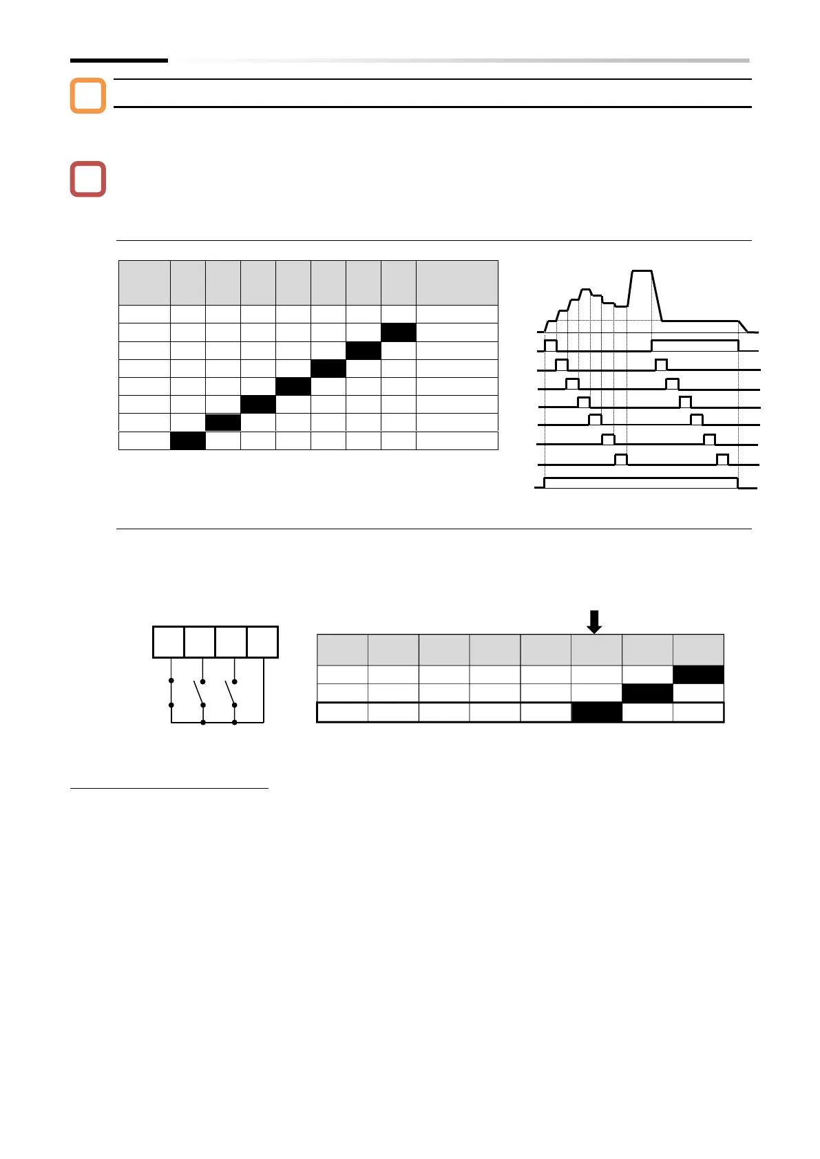
Bit operation mode (command for up to eight speeds: [A019] = 01)
By assigning "Multi-speed Bit [SF1] to [SF7]" to "Input terminal function [C001] to [C007]", it is
possible to switch between multi-speed settings 0 to 7.
When multiple multi-speed bit terminals are turned on simultaneously, the one with the lowest
number is given priority.
In the cells marked with an "x" in the table below, the on/off state of the terminal is ignored.
■ Bit operation mode control table
Frequency
setting
parameter
■ Example of using bit operation mode (when multi-speed 3 is selected)
*
"2nd-motor control [SET]" target parameter. The second control parameter is also subject to setting.
*
Multi-speed 0 is the frequency command set by the "Frequency input source selection [A001]
*1
.
In this example, [C005] = "Multi-speed Bit 1 [SF1]", [C006] = "Multi-speed Bit 2 [SF2]", and [C007] = "Multi-
speed Bit 3 [SF3]", while [SF4] to [SF7] are unassigned. If only input terminal 7 ([SF3]) is turned on, it
corresponds with multi-speed 3, and "Output frequency setting or monitor [F001]" displays the "Multi-
speed 3 [A023]" setting value.

 Loading...


